
Assembling and welding machining method for semi-closed flame tube with deep U-shaped rotary section

A semi-closed, processing method technology, applied in the processing of turbojet engine parts, deep U-shaped rotary cross-section semi-closed flame tube assembly and welding processing field, can solve the difficult to guarantee shape and position tolerance and dimensional accuracy, high shape and position tolerance And dimensional accuracy requirements, the difficulty of positioning and clamping parts, etc., to achieve the effect of improving the quality of welds, ensuring shape and position tolerances, and eliminating welding stress

Active Publication Date: 2021-01-08
SICHUAN AEROSPACE ZHONGTIAN POWER EQUIP CO LTD
View PDF6 Cites 4 Cited by
  • Summary
  • Abstract
  • Description
  • Claims
  • Application Information

AI Technical Summary

Problems solved by technology

Affected by the space structure, the welding operation space is greatly limited, and it is very difficult to position and clamp parts and take out parts after welding. At the same time, the rigidity of thin-walled parts is poor, and cumulative welding stress will be generated in the case of multiple welding. It leads to welding deformation, and it is difficult to guarantee the shape tolerance and dimensional accuracy; in addition, the outer circle at one end of the flame tube and the inner hole at the other end have high shape tolerance and dimensional accuracy requirements, which are difficult to achieve by conventional welding methods

Method used


Image

  • Assembling and welding machining method for semi-closed flame tube with deep U-shaped rotary section
  • Assembling and welding machining method for semi-closed flame tube with deep U-shaped rotary section
  • Assembling and welding machining method for semi-closed flame tube with deep U-shaped rotary section

Examples


Embodiment Construction

[0043] The features and performances of the present invention will be further described in detail below in conjunction with the accompanying drawings.

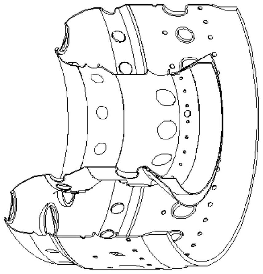
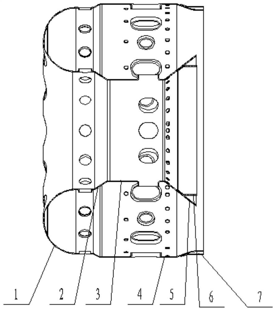
[0044] The structure of the deep U-shaped rotary section semi-closed flame tube is as follows: figure 2 and image 3 shown.

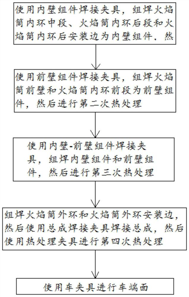
[0045] Such as figure 1 As shown, a deep U-shaped rotary section semi-closed flame cylinder assembly welding processing method includes the following steps:

[0046] S1. Use the welding jig 8 of the inner wall component, assemble and weld the middle section 3 of the inner ring of the flame tube, the rear section 5 of the inner ring of the flame tube and the rear mounting edge 6 of the inner ring of the flame tube as the inner wall component 16, and then perform the first heat treatment;

[0047] S2. Use the front wall component welding jig 9 to assemble and weld the front wall 1 of the flame tube and the front section 2 of the inner ring of the flame tube to form the front wall component 15, and the...


PUM


Abstract

The invention discloses an assembling and welding machining method for a semi-closed flame tube with a deep U-shaped rotary section, and belongs to the technical field of aero-engine machining. The method comprises the steps of firstly, assembling and welding a flame tube inner-ring middle segment, a flame tube inner-ring rear segment and a flame tube inner-ring rear mounting edge to form an innerwall component by using an inner wall component welding clamp, and then conducting first-time heat treatment; secondly, assembling and welding a flame tube front wall and a flame tube inner-ring front segment to form a front wall component by using a front wall component welding clamp, and then conducting second-time heat treatment; assembling and welding the inner wall component and the front wall component by using an inner wall and front wall assembly component welding clamp, and then conducting third-time heat treatment; assembling and welding a flame tube outer ring and a flame tube outer ring mounting edge again, then welding an assembly by using an assembly welding clamp, and then conducting fourth-time heat treatment by using a heat treatment clamp; and finally, lathing an end surface by using a lathing clamp. The method has the advantages of being small in machining difficulty, convenient to operate and reliable in quality.

Description

technical field [0001] The invention relates to the processing of turbojet engine parts, in particular to a deep U-shaped rotary cross-section semi-closed flame tube assembly and welding processing method, which belongs to the technical field of aero-engine processing. Background technique [0002] The combustor flame tube is the area where the aero-engine organizes combustion, and this area has a very high gas temperature. The cooling technology of the flame tube is directly related to the life and reliability of the combustion chamber, and affects the thermal efficiency of the entire engine. With the improvement of the performance of the turbojet engine, the pressure ratio of the engine and the rise of the combustion chamber gradually increase, which makes the wall of the flame tube bear a greater heat load, which puts forward higher requirements for the structure of the flame tube. [0003] There is a new type of flame cylinder, the structure of which is complex, and it ...

Claims


Application Information

Patent Timeline
Patent Type & Authority Applications(China)
IPC IPC(8): B23P15/00
CPCB23P15/00
Inventor 魏林石勇廖东波李朝军肖永印王熠
Owner SICHUAN AEROSPACE ZHONGTIAN POWER EQUIP CO LTD
Learn More