

Microporous seepage structure, airplane anti-icing system and airplane
An anti-icing system and microporous technology, applied in aircraft parts, deicing devices, transportation and packaging, etc., can solve the problems of high energy consumption, damage to the aerodynamic shape of the wing, large thermal inertia, etc., and achieve easy use and technical capabilities and the effect of less judgment requirements and low operating energy consumption
- Summary
- Abstract
- Description
- Claims
- Application Information
AI Technical Summary
Problems solved by technology
Method used
Image

Examples
Embodiment 1
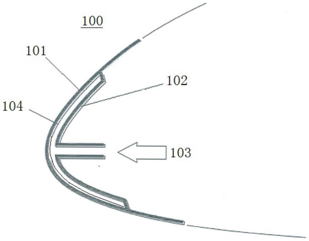
[0022] Such as figure 1 As shown, the embodiment of the present application provides a microporous liquid-permeable structure 100 . The microporous liquid-permeable structure 100 includes a first panel 101 , a second panel 102 and a damping membrane 104 .
[0023] Multiple microholes are uniformly arranged on the first panel 101 . The edge of the second panel 102 is attached to the side of the first panel 101 and can be connected by laser welding. A liquid storage chamber is formed between the first panel 101 and the second panel 102, and the liquid storage chamber is used for storing anti-icing fluid. The second panel 102 is provided with an anti-icing liquid inlet 103 for entering the anti-icing liquid into the liquid storage chamber.
[0024] The damping membrane 104 is disposed on the inner wall of the first panel 101 , and the damping membrane 104 covers all micropores on the inner wall of the first panel 101 . The damping diaphragm 104 is a porous diaphragm of the ex...
Embodiment 2
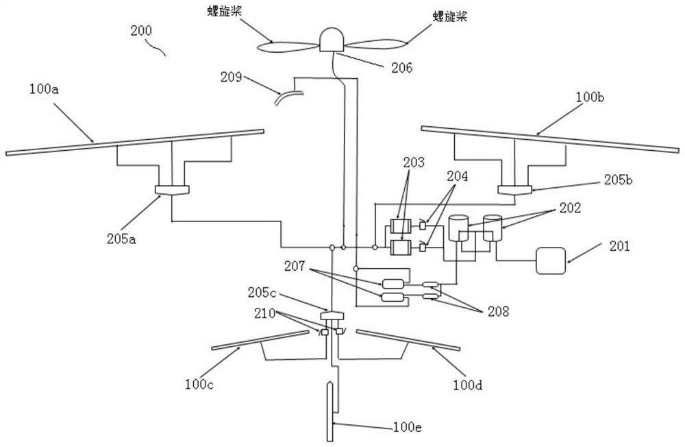
[0027] Such as figure 2 As shown, this embodiment provides an aircraft anti-icing system 200 . The aircraft anti-icing system 200 includes an anti-icing liquid tank 201 , a quantitative pump 202 , a filter 203 and the microporous liquid-permeable structure 100 as described above.
[0028] The anti-icing fluid tank 201 is used to store the anti-icing fluid, and the anti-icing fluid stored in the anti-icing fluid tank 201 should ensure that the aircraft anti-icing system 200 can operate normally for at least about 150 minutes. The size of the anti-icing fluid tank 201 can be adjusted according to requirements.
[0029] The quantitative pump 202 is connected to the anti-icing fluid tank 201 to provide anti-icing fluid with a certain pressure and flow rate for the anti-icing of the fuselage. There may be multiple quantitative pumps 202. In this embodiment, there are two quantitative pumps 202, one as the main pump and one as the auxiliary pump. The flow rate of the quantitativ...
Embodiment 3
[0037] This embodiment provides an aircraft, including the above aircraft anti-icing system 200 . There are multiple microporous liquid-permeable structures 100, among which, the first microporous liquid-permeable structure 100a is bent into the shape of the leading edge of the left wing and arranged on the left wing, and the second microporous liquid-permeable structure 100b is bent into the shape of the right wing The shape of the leading edge is set on the right wing, the shape of the third microporous liquid seepage structure 100c bent into the shape of the leading edge of the left flat tail is set on the left flat tail, and the fourth microporous liquid seepage structure 100d is bent into the shape of the leading edge of the right flat tail and set on the right wing. For the horizontal tail, the fifth microporous liquid-permeable structure 100e is bent into the shape of the leading edge of the vertical tail and arranged on the vertical tail.
[0038] The first distributio...
PUM
| Property | Measurement | Unit |
|---|---|---|
| Aperture | aaaaa | aaaaa |
| Spacing | aaaaa | aaaaa |
Abstract
Description
Claims
Application Information