
Automatic buckling machine

An automatic buckle and material machine technology, applied in the field of optical technology and automation, can solve problems such as not meeting the efficiency requirements of camera modules, and achieve the effect of increasing output per unit area, improving efficiency, and improving product yield

Active Publication Date: 2021-01-08
NINGBO SUNNY OPOTECH CO LTD
View PDF5 Cites 1 Cited by
  • Summary
  • Abstract
  • Description
  • Claims
  • Application Information

AI Technical Summary

Problems solved by technology

However, this conveyor belt-based assembly line still cannot meet the efficiency requirements for the automatic buttoning operation of the camera module.

Method used


Image

  • Automatic buckling machine
  • Automatic buckling machine
  • Automatic buckling machine

Examples


Embodiment Construction

[0063] For a better understanding of the application, various aspects of the application will be described in more detail with reference to the accompanying drawings. It should be understood that these detailed descriptions are descriptions of exemplary embodiments of the application only, and are not intended to limit the scope of the application in any way. Throughout the specification, the same reference numerals refer to the same elements. The expression "and / or" includes any and all combinations of one or more of the associated listed items. It should be noted that in this specification, expressions of first, second, etc. are only used to distinguish one feature from another, and do not represent any limitation on the features. Accordingly, a first body discussed hereinafter may also be referred to as a second body without departing from the teachings of the present application. In the drawings, the thickness, size and shape of objects have been slightly exaggerated for...


PUM


Abstract

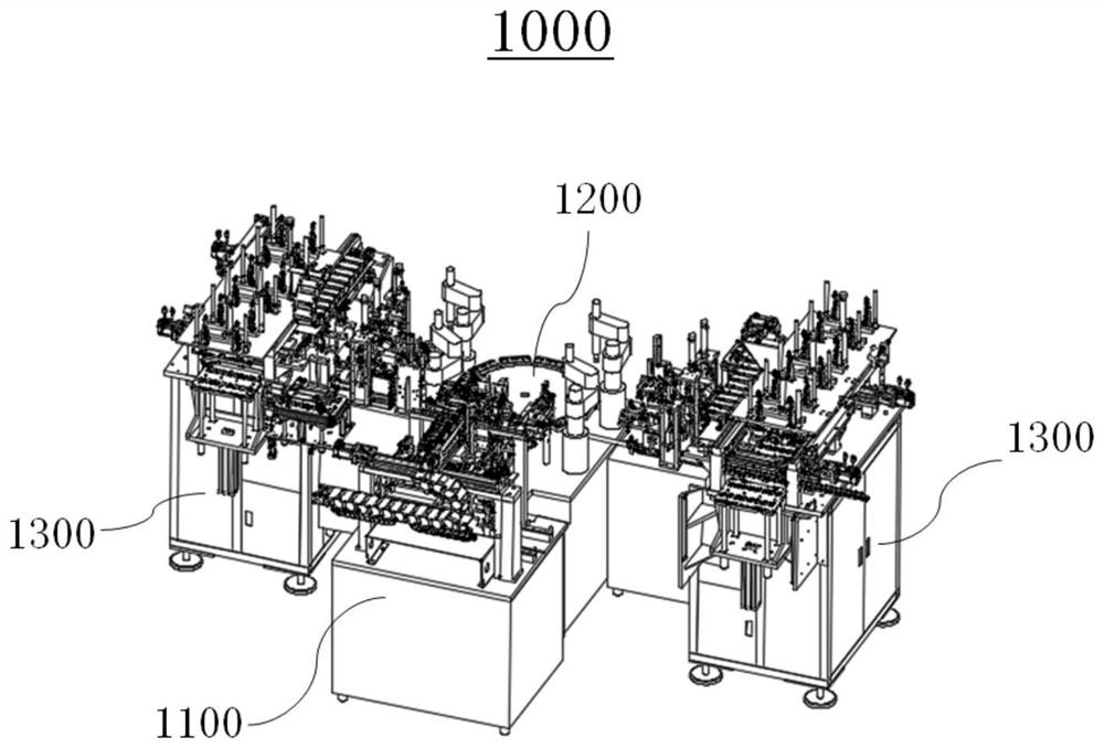
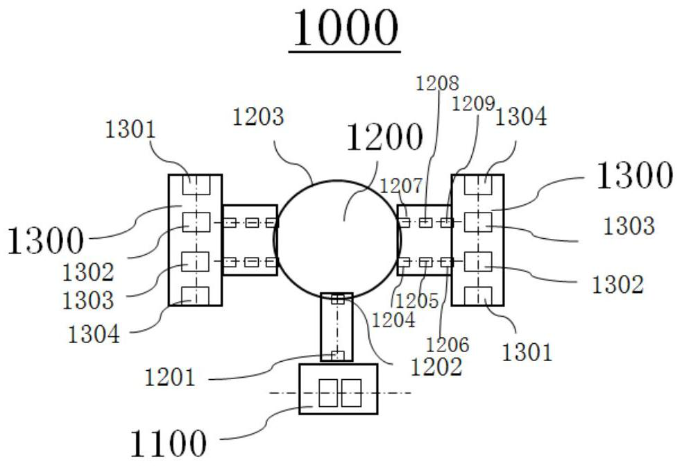
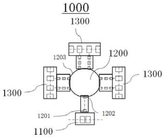
The invention provides an automatic buckling machine. The automatic buckling machine comprises photographing buckling equipment and carrier jointed board feeding and discharging equipment, wherein thecarrier jointed board feeding and discharging equipment comprises a jointed board feeding position, a distributing position, a collecting position and a discharging position which are arranged alonga jointed board displacement axis; the photographing buckling equipment comprises a plurality of positioning clamps, a photographing buckling mechanism, a carrier feeding mechanism and a carrier discharging mechanism, wherein the positioning clamps are arranged along the displacement circumference of a carrier and can rotate along the circumference; the photographing buckling mechanism comprises abuckling position which is coupled with the displacement circumference of the carrier; the carrier feeding mechanism comprises a carrier feeding position, a feeding power-on test position and a feeding base which are arranged along a feeding displacement axis of the carrier; and the carrier discharging mechanism is provided with a similar discharging displacement axis and a corresponding positionor structure, and the two ends of the feeding and discharging displacement axes are coupled with the displacement circumference of the carrier and the jointed board displacement axis respectively. According to the automatic buckling machine, high-automation automatic buckling of a camera module can be realized; and the automatic buckling machine is more compact, so that the yield per unit area isincreased.

Description

technical field [0001] The invention relates to the fields of optical technology and automation technology, in particular, the invention relates to an automatic buttoning machine. Background technique [0002] With the continuous improvement of the functions of smart products, the camera module has become one of the main components of the mobile terminal. The performance test of the camera module before installation is an important process to ensure the photography function of the subsequent mobile terminal. In this process, the camera module needs to be connected to external testing equipment through the module connector to complete performance testing and OTP programming. In the prior art, a single manual detection method is mostly used to detect the camera module, which has low work efficiency and high labor intensity. At the same time, it is difficult to accurately dock dense pins with the naked eye during the manual insertion process, and the alignment is not accurate o...

Claims


Application Information

Patent Timeline
IPC IPC(8): B65G47/90B65G47/91B65G47/74
CPCB65G47/902B65G47/914B65G47/74
Inventor 李振锋吴兵强耿永
Owner NINGBO SUNNY OPOTECH CO LTD
Learn More