

Unloading valve, combination valve comprising unloading valve and combination valve type buffer oil cylinder
A technology of unloading valve and combination valve, applied in the field of hydraulic oil cylinder and hydraulic valve, can solve the problems of difficulty in throttle control, low buffer quality, large mechanical impact and impact, avoid power consumption and system heating, and improve buffer effect. , The effect of protecting the hydraulic system
- Summary
- Abstract
- Description
- Claims
- Application Information
AI Technical Summary
Problems solved by technology
Method used
Image

Examples
Embodiment 1
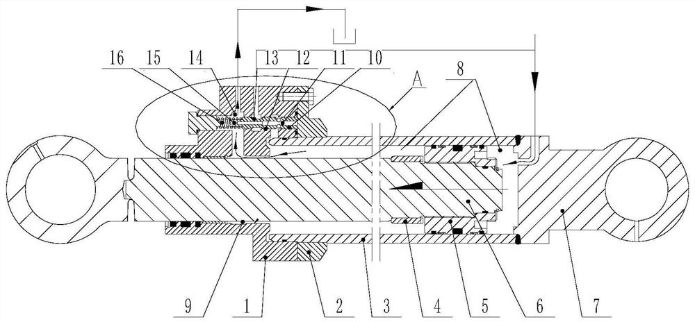
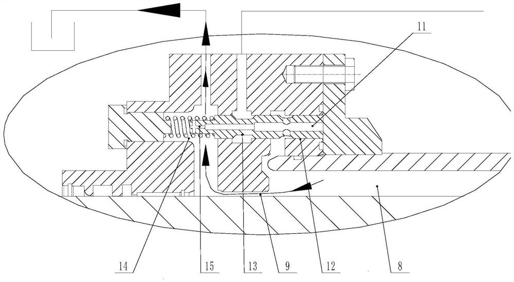
[0047] Such as Figure 1-4 As shown, an unloading valve, a combination valve including the unloading valve and a combined valve type buffer oil cylinder, the unloading valve and the oil cylinder are used together to realize the unloading buffer function of the oil cylinder, including a valve body, a valve core 10 and a return Position spring 16, with a valve hole 12 on the valve body, the valve core is fitted in the valve hole, the drive cavity 11 of the valve core and the spring cavity 14 of the valve core are formed at the two ends of the valve hole respectively, and the return spring is arranged on the spring In the chamber, one end is compressed against the bottom of the spring chamber, and the other end is compressed against one end of the valve core, and the valve core is pressed against the bottom of the drive chamber by the thrust of the return spring; The core is also provided with a damping hole 15 and an unloading groove 13. The driving chamber of the valve hole com...
Embodiment 2
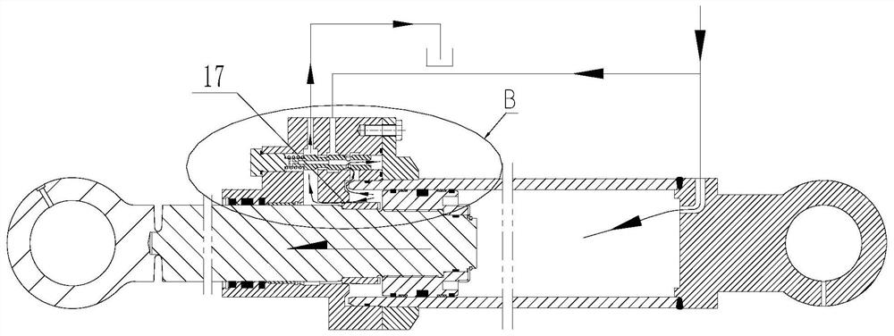
[0054] Such as Figure 5 , Figure 6 As shown in the figure, a combination valve type cushioning oil cylinder is provided with a combination valve only in the cylinder chamber at one end of the cylinder bottom, and the combination valve is integrated on the bottom of the cylinder, which can realize the cushioning of the oil cylinder at the bottom end of the cylinder. Figure 5 and Figure 6 The structure is similar, only the location of the unloading valve is different. Compared with Example 1, the main difference is that: the valve hole of the unloading valve and the buffer chamber of the throttle valve are set on the bottom of the cylinder, and the buffer plug of the throttle valve is set at the center of the bottom of the piston rod. Similar to Example 1, it will not be repeated here.
Embodiment 3
[0056] Such as Figure 7 As shown, a combination valve type buffer oil cylinder is equipped with combination valves at both ends of the oil cylinder, which can realize the buffer when the piston at any end of the oil cylinder is close to the end of the cylinder stroke. This embodiment is a composite structure of Embodiment 1 and Embodiment 2, which can realize the two-way buffering function of the oil cylinder. During the working process of the oil cylinder, when the piston is close to the stroke end of one end of the oil cylinder, only the combination valve arranged at the end of the oil cylinder is activated to play the buffer function.
PUM
 Abstract
Description
Claims
Application Information