Hydraulic engineering pipeline maintenance device

A technology for water conservancy projects and pipelines, which is used in pipeline laying and maintenance, lifting devices, pipe components, etc., can solve the problems of difficult alignment, low work efficiency, and insufficient stability of manual pipe support, and achieves simple structure, convenient transportation, The effect of reducing space occupancy

Active Publication Date: 2021-01-08
YELLOW RIVER CONSERVANCY TECHN INST
View PDF6 Cites 0 Cited by
  • Summary
  • Abstract
  • Description
  • Claims
  • Application Information

AI Technical Summary

Problems solved by technology

[0005] In view of the above situation, in order to overcome the defects of the prior art, the present invention provides a water conservancy engineering pipeline maintenance device, which effectively solves the problem of manual maintenance during pipeline replacement in the prior art. The support tube is not easy to align, not stable enough, and the work efficiency is low

Method used


Image

  • Hydraulic engineering pipeline maintenance device
  • Hydraulic engineering pipeline maintenance device
  • Hydraulic engineering pipeline maintenance device

Examples


Embodiment 1

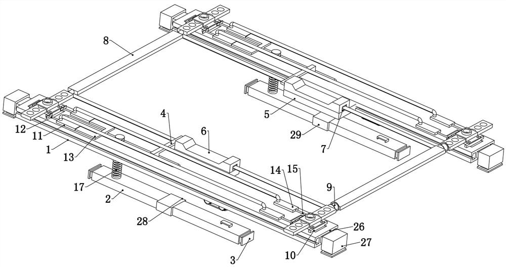
[0041] Embodiment 1, the present invention is a water conservancy pipeline maintenance device, which is characterized in that it includes two support beams 1, the two support beams 1 are placed on the ground and span the excavated pipe culvert, and the two support beams 1 are used for subsequent The structure provides a fixed foundation, the lower ends of the two supporting beams 1 slide up and down and are connected with a positioning beam 2, and the positioning beam 2 is placed in the excavated pipe culvert, and both ends of the two positioning beams 2 are fixedly connected with positioning beams. The hydraulic cylinder 3, the two positioning hydraulic cylinders 3 on each positioning beam 2 are synchronously controlled by the positioning hydraulic pump fixedly connected to the corresponding positioning beam 2, the positioning hydraulic pump can drive the two positioning hydraulic cylinders 3 to extend out synchronously, The two positioning hydraulic cylinders 3 are in contact...

Embodiment 2

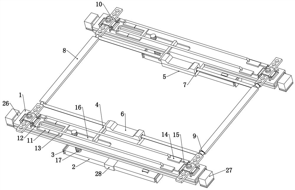
[0045] Embodiment 2. On the basis of Embodiment 1, this embodiment provides a structure in which the vertical beam 8 moves synchronously with the positioning beam 2, so that after the bearing platform 5 breaks away from the support of the crossties 6, the replacement pipe is still located between the two vertical beams. The central position between the beams 8, so as to prevent the position of the replacement pipe from shifting when the steel wire rope supports the replacement pipe. For details, refer to image 3 , Figure 6 , Figure 7 , the two ends of the upper end of the supporting beam 1 are slidably connected to the vertical beam base 10, and one end of the two vertical beams 8 is fixedly connected to the vertical beam base 10, and the two ends of each vertical beam 8 are fixedly connected to the vertical beam base 10 respectively. On the two vertical beam bases 10 on the two supporting beams 1, refer to the specific fixing method Figure 6 , Figure 7 , the two ends ...

Embodiment 3

[0050] Embodiment three, on the basis of embodiment two, refer to Figure 5 , the two positioning bases 16 are slidably connected inside the two supporting beams 1, and the two positioning bases 16 are slidingly connected inside the supporting beam 1 and the lower end faces thereof are flush with the lower end faces of the supporting beams. The gear arm 4 and the drive push rod 13 are fixedly connected to the positioning base 16, that is, the movement of the positioning base 16 drives the gear arm 4 and the drive push rod 13 to move synchronously;

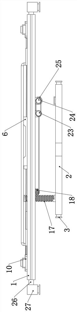
[0051] The positioning beam 2 is rotatably connected with a positioning screw 17, and the positioning screw 17 passes through the adjacent positioning base 16 and is screwed with it, and the positioning beam 2 is fixedly connected with a positioning motor. The positioning motor is connected with the positioning screw 17. Specifically, the positioning base 16 is provided with a threaded hole, and the positioning screw 17 passes thro...


PUM


Abstract

The invention relates to a hydraulic engineering pipeline maintenance device. The problems that in the prior art, when a pipeline is replaced, during manual pipe supporting, alignment is not easy, thepipeline is not stable enough, and working efficiency is low are effectively solved. According to the technical scheme for solution, the device comprises two supporting cross beams, positioning crossbeams are connected to the lower ends of the two supporting cross beams in an up-down sliding manner, positioning hydraulic cylinders are fixedly connected to the two ends of each of the two positioning cross beams, the two positioning hydraulic cylinders on each positioning cross beam are synchronously controlled by a positioning hydraulic pump fixedly connected to the corresponding positioningcross beam, and the upper ends of the two positioning cross beams are fixedly connected with stop arms penetrating through the corresponding supporting cross beams. The device is simple in structure and convenient to operate, left-right alignment of the pipeline is achieved through the positioning cross beams, the stop arms, a bearing platform and a sleeper, up-down alignment of the pipeline is achieved through an infrared transmitter and an infrared receiver, and therefore alignment of a replacement pipe and an original pipeline is guaranteed, operation is convenient, and practicability is high.

Description

technical field [0001] The invention relates to the technical field of water conservancy engineering, in particular to a maintenance device for water conservancy engineering pipelines. Background technique [0002] In the construction of water conservancy buildings, water pipes are an indispensable part. Water pipes are important tools for water delivery, drainage and flood discharge. Therefore, water pipes are extremely widely used in water conservancy construction. Among them, in the maintenance process of water conservancy pipelines, replacing pipelines is a common means. [0003] In the maintenance of water conservancy pipelines, after the pipe culverts are dug and the pipes are cut, it is very difficult to align the pipes, so it is often difficult and time-consuming to replace the pipes. The main reason is that in the prior art, the replacement of pipes usually uses a crane to lift the pipes, and manually straighten the pipes and prevent the pipes from swinging. Due to...

Claims


Application Information

Patent Timeline
IPC IPC(8): F16L1/10F16L55/18B66F7/02B66F7/00
CPCF16L1/10F16L55/18B66F7/02B66F7/025
Inventor 雷恒李颖杨春景周志琦万晓丹高新江秦净净周晓岚卫宗超轩鹏胜
Owner YELLOW RIVER CONSERVANCY TECHN INST
Why Eureka
Try Eureka