Control method of pure gas jet wind tunnel
A pure gas and control method technology, applied in the field of wind tunnel test, can solve problems such as damage, equipment ablation, heat storage body floating, etc., and achieve the effects of improving test efficiency, saving energy and avoiding damage
- Summary
- Abstract
- Description
- Claims
- Application Information
AI Technical Summary
Problems solved by technology
Method used
Image
Examples
Embodiment 1
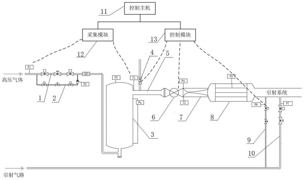
[0038] Such as figure 1 As shown, an automatic control method of a pure gas jet wind tunnel is used in a regenerative pure gas jet wind tunnel. From the completion of the heat storage test to the end of the high temperature valve closing test, the time intervals are t0, t1, t2, t3, t4 , t5, t6, t7, t8 represent each time node, and the method includes the following steps:
[0039] (1) Test ready stage t0: The temperature gradient distribution of the heat storage tank reaches the expectation, that is, the heat storage is completed, and the wind tunnel test is ready;
[0040] (2) Low-flow inflation stage t1~t2: Press pure gas into the heat storage tank at a constant flow rate from the small-flow inflation path. At this time, all valves connected to the heat storage tank, including the high-temperature opening and closing device and other valves, are closed. state, when the pressure value of the heat storage tank is higher than the preset threshold α, the small flow charging stag...
Embodiment 2
[0058] On the basis of Example 1, different from Example 1, such as figure 1 As shown, an automatic control method of a pure gas jet wind tunnel is used for a regenerative pure gas free jet wind tunnel. According to the results of multiple debugging, the method includes the following steps:
[0059] (1) In the test preparation stage, the temperature gradient distribution of the heat storage tank reaches 1700K at the upper end of the heat storage tank and 800K at the lower end, forming a gradient distribution, and the wind tunnel test is ready.
[0060] (2) In the small flow gas charging stage, in order to ensure that the heat storage bricks in the heat storage tank do not float, a differential pressure sensor P is installed to measure the pressure difference between the upper and lower sides of the heat storage tank aIt can not exceed 20KPa. According to the flow calculation, the small flow gas charging path adopts a 4mm sonic flowmeter, and the upstream pressure is set to 8MP...
PUM
 Abstract
Description
Claims
Application Information
 - R&D
- Intellectual Property
- Life Sciences
- Materials
- Tech Scout
- Unparalleled Data Quality
- Higher Quality Content
- 60% Fewer Hallucinations
Browse by: Latest US Patents, China's latest patents, Technical Efficacy Thesaurus, Application Domain, Technology Topic, Popular Technical Reports.
© 2025 PatSnap. All rights reserved.Legal|Privacy policy|Modern Slavery Act Transparency Statement|Sitemap|About US| Contact US: help@patsnap.com


