
Battery pressurizing device and battery pressurizing method

A pressurizing device and battery technology, applied to primary batteries, equipment for manufacturing primary batteries, secondary batteries, etc., can solve problems that affect the quality of battery processing and the bottom of the battery cannot be pressured

Pending Publication Date: 2021-01-08
深圳鼎阳智能电气有限公司
View PDF0 Cites 1 Cited by
  • Summary
  • Abstract
  • Description
  • Claims
  • Application Information

AI Technical Summary

Problems solved by technology

[0002] At present, when the two surfaces of the battery are pressurized, a silicone pad is used, and the silicone pad is placed in an inverted U shape. When the battery is placed in this way, the bottom of the battery is not supported, and it is in contact with the base of the pressurizing device. Problems that affect the quality of battery processing
Even if the inverted U-shaped silicone pad is set long enough, there is still a problem that the bottom of the battery cannot be pressed because there is a gap between the bottom of the pressing plate and the base because the bottom of the pressing plate is not in contact with the base.

Method used


Image

  • Battery pressurizing device and battery pressurizing method
  • Battery pressurizing device and battery pressurizing method
  • Battery pressurizing device and battery pressurizing method

Examples


Embodiment Construction

[0026] The present invention will be further described in detail below through specific embodiments in conjunction with the accompanying drawings. Wherein, similar elements in different implementations adopt associated similar element numbers. In the following implementation manners, many details are described for better understanding of the present application. However, those skilled in the art can readily recognize that some of the features can be omitted in different situations, or can be replaced by other elements, materials, and methods. In some cases, some operations related to the application are not shown or described in the description, this is to avoid the core part of the application being overwhelmed by too many descriptions, and for those skilled in the art, it is necessary to describe these operations in detail Relevant operations are not necessary, and they can fully understand the relevant operations according to the description in the specification and genera...


PUM

PropertyMeasurementUnit
Densityaaaaaaaaaa
Thicknessaaaaaaaaaa

Abstract

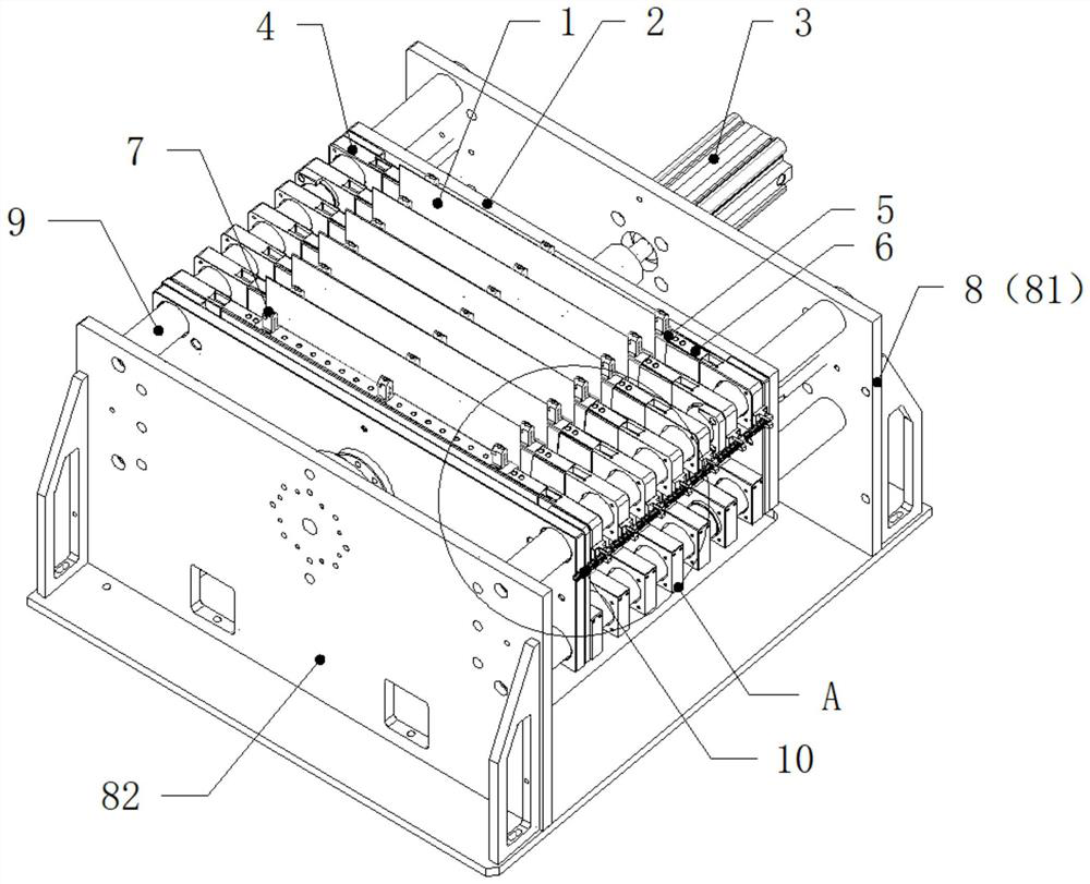
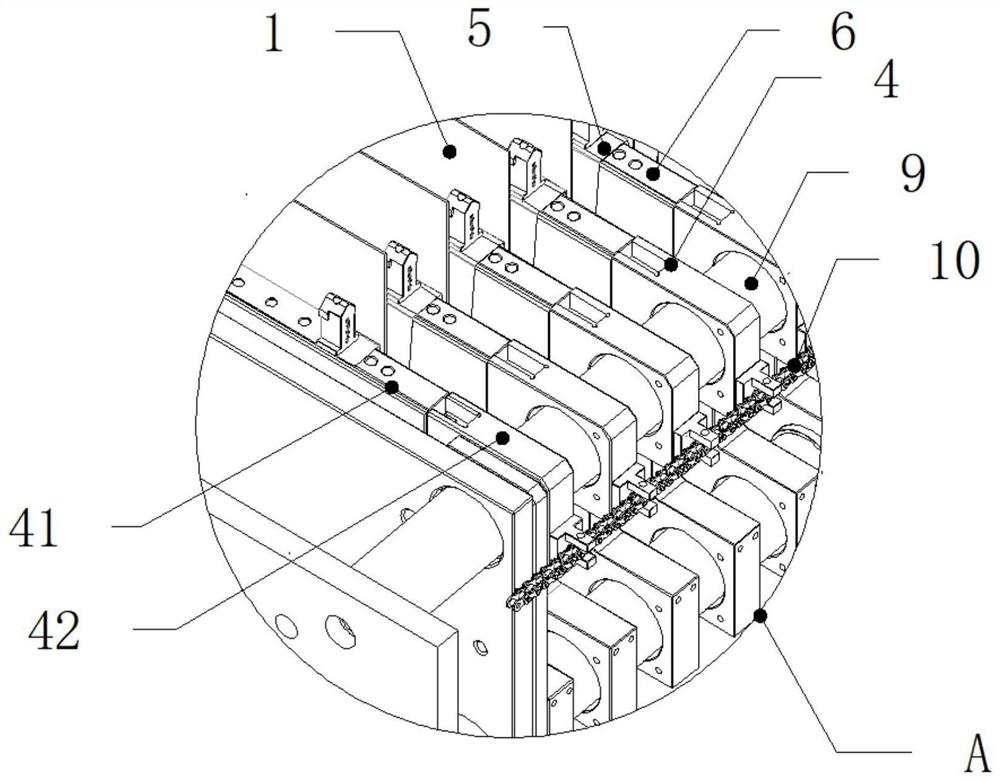
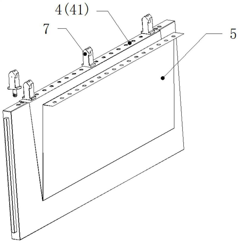
A battery pressurizing device comprises a driving part, a sliding plate, a battery cell layer, a buffer layer, a fixed plate, a guide shaft and a base. The sliding plate can slide in the axial direction of the guide shaft. The battery cell layer is V-shaped and is detachably fixed between the two sliding plates, the V-shaped battery cell layer is used for placing a battery, and the bottom of the V-shaped battery cell layer 5 is not lower than the bottoms of the sliding plates 4. A buffer layer is fixed between the sliding plate and the battery. Fixing plates are arranged at the two sides of the base respectively, and a guide shaft is fixed between the fixing plates. Through holes are formed in the fixing plates, a guide shaft is fixed to one side of the fixing plate, the driving part is arranged at the other side, and the connecting rod penetrates through the through hole to be fixedly connected with the sliding plate. As the battery cell layer is of the V-shaped structure, the bottomof the battery cannot fall on the bottom surface due to gravity, and the whole part of the battery is arranged on the battery cell layer. Pressure can be applied to the whole surface of the battery. Due to the fact that the density of the elastic buffer layer is low, enough wriggling space exists in the buffer layer, the low point of the plane of the sliding plate is better filled, and the surfaceof the battery is subjected to uniform pressure.

Description

technical field [0001] The invention relates to the technical field of battery manufacturing, in particular to a battery pressurizing device and a battery pressurizing method. Background technique [0002] At present, when the two surfaces of the battery are pressurized, a silicone pad is used, and the silicone pad is placed in an inverted U shape. When the battery is placed in this way, the bottom of the battery is not supported, and it is in contact with the base of the pressurizing device. It is easy to have the bottom of the battery that cannot be pressured Problems that affect the quality of battery processing. Even if the inverted U-shaped silicone pad is set long enough, there is still a problem that pressure cannot be applied to the bottom of the battery because the bottom of the pressing plate is not in contact with the base and there is a gap between the bottom of the pressing plate and the base. Contents of the invention [0003] The present invention provides ...

Claims


Application Information

Patent Timeline
IPC IPC(8): H01M6/00H01M10/04
CPCH01M6/005H01M10/0481Y02E60/10Y02P70/50
Inventor 张瑛胡青松丁团员刘国雄魏建刚强志杰徐福斌阳如坤
Owner 深圳鼎阳智能电气有限公司
Learn More