

Automobile inverter
A technology for inverters and automobiles, which is applied to the transformation of equipment structural parts, conversion of AC power input to DC power output, cooling/ventilation/heating transformation, etc., which can solve the problem of poor exhaust heat dissipation, inconvenient installation, disassembly and maintenance, etc. problems, to achieve the effect of easy installation and disassembly maintenance, convenient operation and simple structure
- Summary
- Abstract
- Description
- Claims
- Application Information
AI Technical Summary
Problems solved by technology
Method used
Image

Examples
Embodiment 1
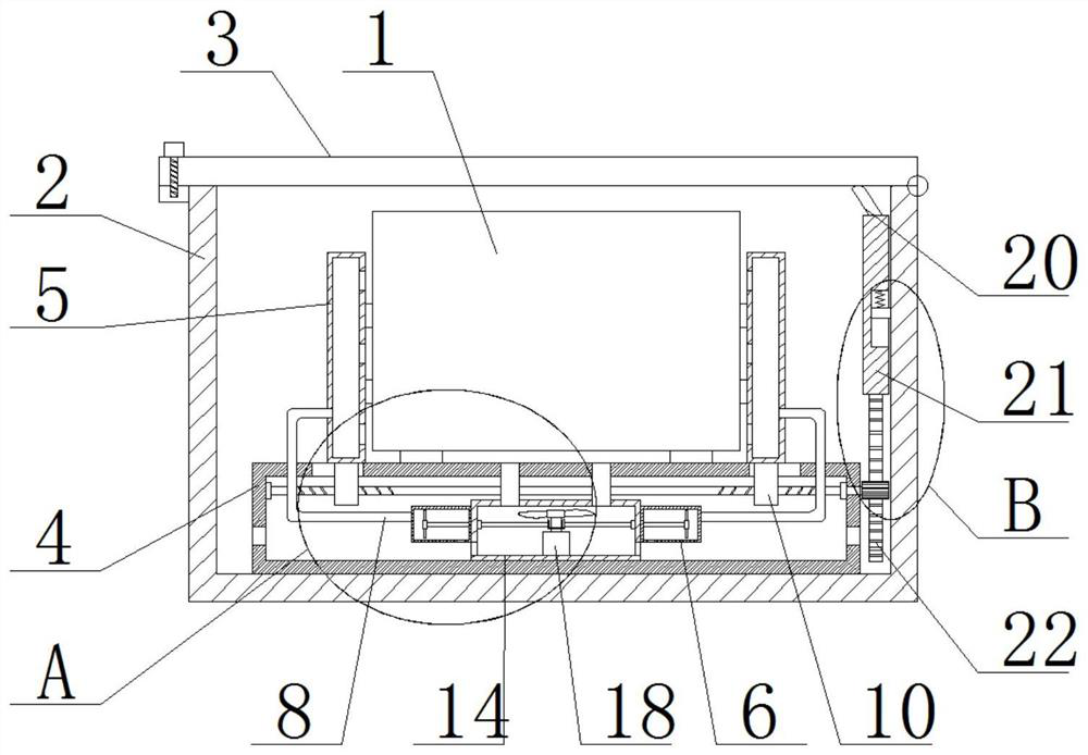
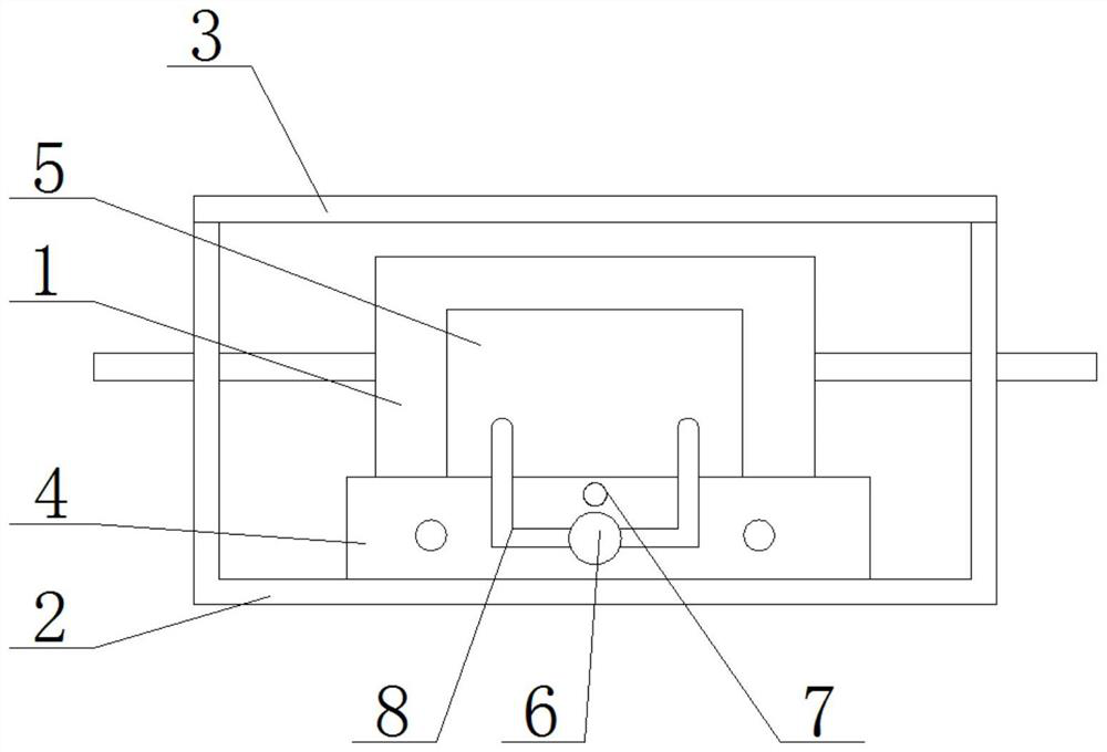
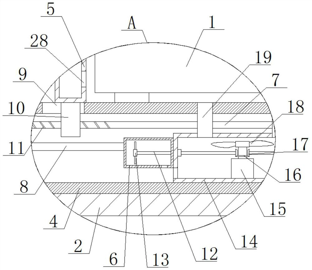
[0026] refer to Figure 1-5 , an automobile inverter, comprising an inverter body 1 and an installation box 2, a vent box 4 is fixedly installed on the inner wall of the bottom of the installation box 2, and a plurality of air holes are opened on the outside of the vent box 4, and the inverter body 1 is placed On the top of the ventilation box 4, two sliding holes 9 are symmetrically opened on the top of the ventilation box 4, and a slider 10 is slidably installed in the two sliding holes 9, and a heat dissipation fixing box 5 is fixedly installed on the top of the two sliders 10. , the sides of the two heat dissipation fixed boxes 5 that are close to each other are fixedly installed with a collision pad 27, and the collision pad 27 is in contact with the inverter body 1, and the bottom inner wall of the ventilation box 4 is fixedly connected with a blowing box 14, and the blowing box 14 A motor 15 is fixedly mounted on the inner wall of the bottom of the motor 15, a motor sha...
Embodiment 2
[0035] refer to Figure 1-5, an automobile inverter, comprising an inverter body 1 and an installation box 2, the bottom inner wall of the installation box 2 is fixedly installed with a ventilating box 4 by welding, the outside of the ventilating box 4 is provided with a plurality of air holes, and the inverter body 1 is placed on the top of the ventilation box 4, and the top of the ventilation box 4 is symmetrically provided with two sliding holes 9, and the sliders 10 are slidably installed in the two sliding holes 9, and the tops of the two sliders 10 are fixed and installed by welding. The heat dissipation fixed box 5, the sides of the two heat dissipation fixed boxes 5 close to each other are fixed with a collision pad 27 by welding, the collision pad 27 is in contact with the inverter body 1, and the bottom inner wall of the ventilation box 4 is fixed and connected with a blower. Air box 14, motor 15 is fixedly installed by welding on the bottom inner wall of blowing box...
PUM
 Abstract
Description
Claims
Application Information