Fault detection method, device and system for communication line
A communication line and fault detection technology, which is applied in transmission systems, electromagnetic wave transmission systems, electrical components, etc., can solve problems such as inability to accurately and effectively detect communication lines, affect the production safety and stable operation of power systems, and achieve production safety and stability. running effect
- Summary
- Abstract
- Description
- Claims
- Application Information
AI Technical Summary
Problems solved by technology
Method used
Image

Examples
Embodiment 1
[0030] According to an embodiment of the present invention, an embodiment of a fault detection method for a communication line is provided. It should be noted that the steps shown in the flow chart of the accompanying drawings can be executed in a computer system such as a set of computer-executable instructions, Also, although a logical order is shown in the flowcharts, in some cases the steps shown or described may be performed in an order different from that shown or described herein.
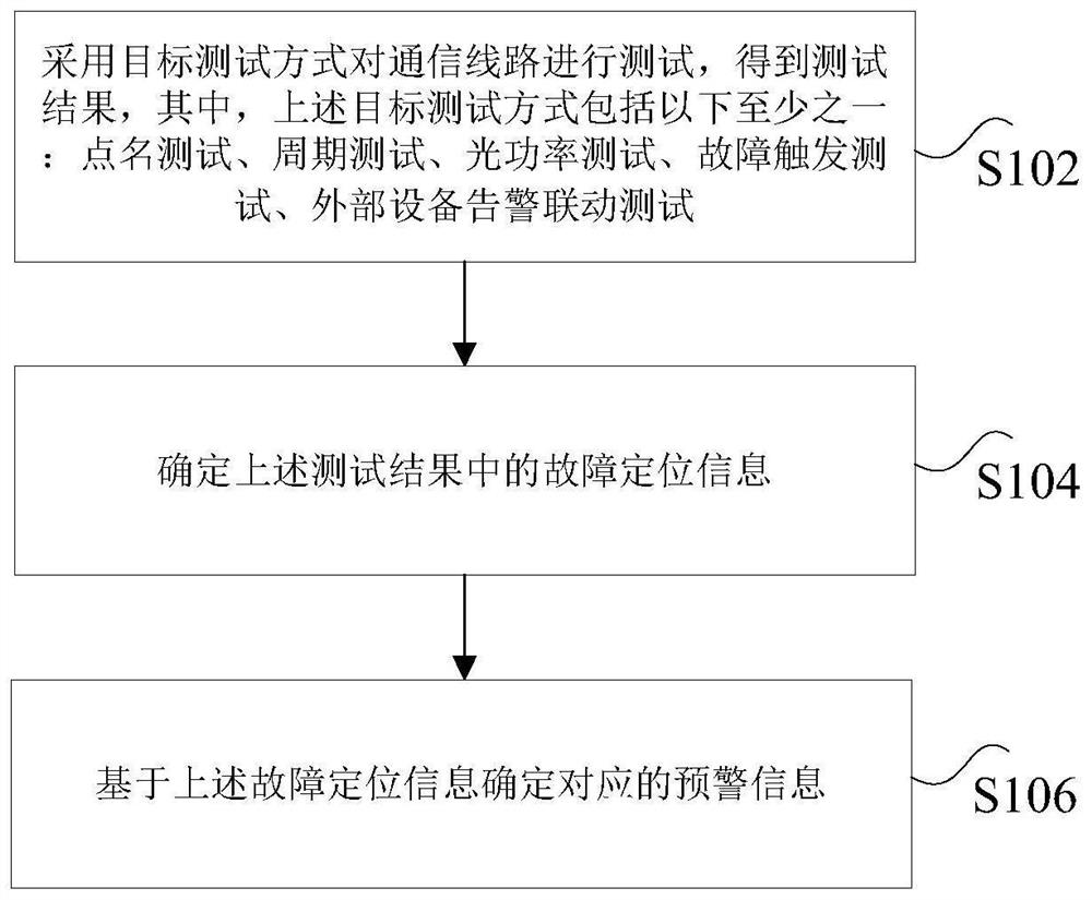
[0031] figure 1 It is a flowchart of a fault detection method for a communication line according to an embodiment of the present invention, such asfigure 1 As shown, the method includes the following steps:
[0032] Step S102, using a target test method to test the communication line to obtain a test result, wherein the target test method includes at least one of the following: roll call test, periodic test, optical power test, fault trigger test, and external device alarm linkage test;
[...
Embodiment 2
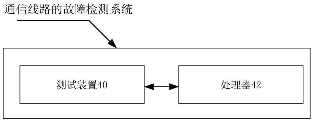
[0093] According to an embodiment of the present invention, a system embodiment for implementing the above communication line fault detection method is also provided, figure 2 is a schematic structural diagram of a communication line fault detection system according to an embodiment of the present invention, such as figure 2 As shown, the fault detection system of the above-mentioned communication line includes: a testing device 40 and a processor 42, wherein:
[0094] The test device 40 is used to test the communication line in a target test mode to obtain a test result, wherein the target test mode includes at least one of the following: roll call test, periodic test, optical power test, fault trigger test, external equipment alarm linkage Testing; the processor 42 is connected to the testing device 40 and is used to determine the fault location information in the test results, and determine the corresponding early warning information based on the fault location informatio...
Embodiment 3
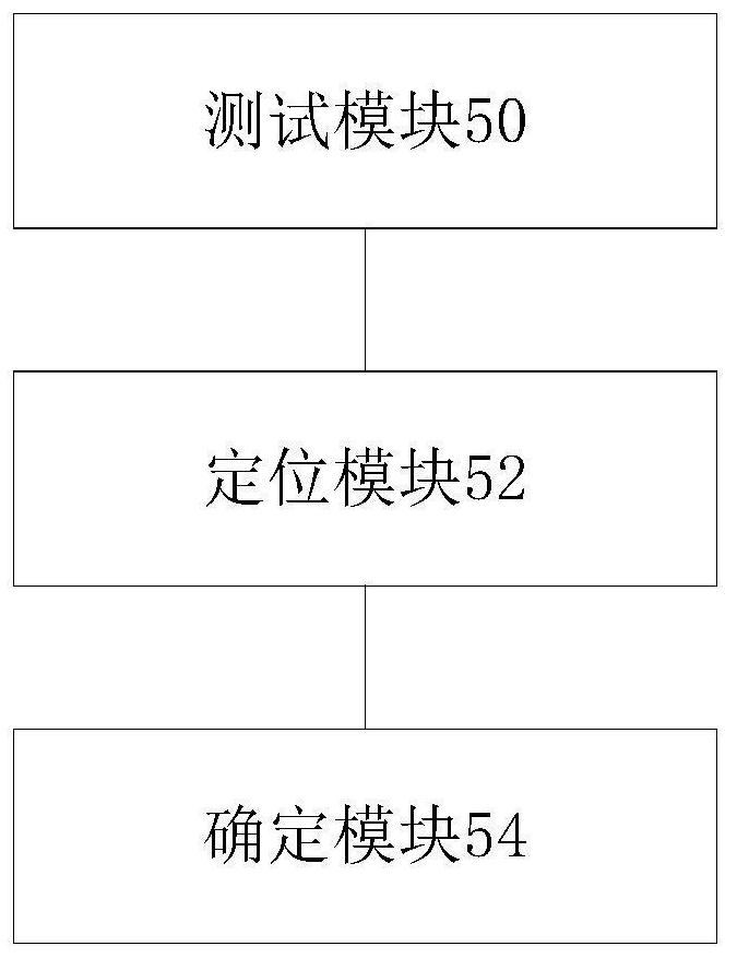
[0103] According to an embodiment of the present invention, a device embodiment for implementing the above communication line fault detection method is also provided, image 3 is a schematic structural diagram of a communication line fault detection device according to an embodiment of the present invention, as shown in image 3 As shown, the fault detection device of the above-mentioned communication line includes: a test module 50, a positioning module 52 and a determination module 54, wherein:
[0104] The test module 50 is used to test the communication line in a target test mode to obtain a test result, wherein the target test mode includes at least one of the following: roll call test, periodic test, optical power test, fault trigger test, and external device alarm linkage Testing; a location module 52, configured to determine the fault location information in the above test results; a determination module 54, used to determine corresponding early warning information bas...
PUM
 Abstract
Description
Claims
Application Information
 - R&D
- Intellectual Property
- Life Sciences
- Materials
- Tech Scout
- Unparalleled Data Quality
- Higher Quality Content
- 60% Fewer Hallucinations
Browse by: Latest US Patents, China's latest patents, Technical Efficacy Thesaurus, Application Domain, Technology Topic, Popular Technical Reports.
© 2025 PatSnap. All rights reserved.Legal|Privacy policy|Modern Slavery Act Transparency Statement|Sitemap|About US| Contact US: help@patsnap.com