Convenient-to-maintain plate shearing machine for hinge machining

A shearing machine and hinge technology, applied in metal processing equipment, shearing machine equipment, shearing devices, etc., can solve problems such as fracture separation, plate deviation, unqualified sheared products, etc., to achieve convenient shearing, fixation and prevention Effect

Inactive Publication Date: 2021-01-12
刘帅
View PDF0 Cites 2 Cited by
  • Summary
  • Abstract
  • Description
  • Claims
  • Application Information

AI Technical Summary

Problems solved by technology

[0002] The plate shearing machine is a machine that uses one blade to make a reciprocating linear motion relative to the other blade to cut the plate. It uses the moving upper blade and the fixed lower blade to apply shear to metal plates of various thicknesses with a reasonable blade gap. The shearing machine belongs to a kind of forging machinery. When the existing shearing machine is placed, if there is a slight inclination, the support seat cannot be adjusted, resulting in the adjustment of the plate. Unqualified cut products will appear during shearing, and when placing the plate that needs to be cut, it needs to be placed manually. In this case, it is very easy to be dangerous. At the same time, the existing shearing machine is cutting the plate When the plate will deviate, which will lead to the unqualified sheared products, and once the internal failure occurs, it cannot be easily repaired

Method used


Image

  • Convenient-to-maintain plate shearing machine for hinge machining
  • Convenient-to-maintain plate shearing machine for hinge machining
  • Convenient-to-maintain plate shearing machine for hinge machining

Examples


Embodiment Construction

[0026] The following will clearly and completely describe the technical solutions in the embodiments of the present invention with reference to the accompanying drawings in the embodiments of the present invention. Obviously, the described embodiments are only some, not all, embodiments of the present invention. Based on the embodiments of the present invention, all other embodiments obtained by persons of ordinary skill in the art without making creative efforts belong to the protection scope of the present invention.

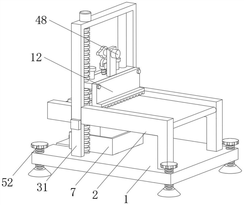
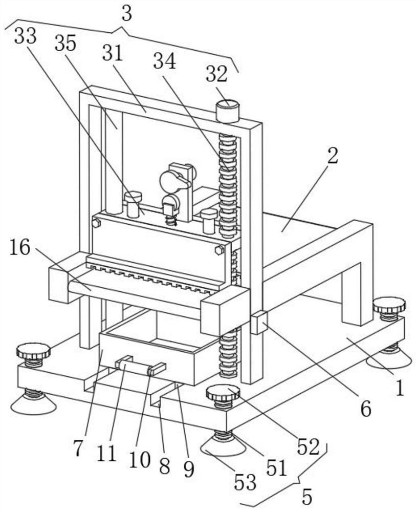
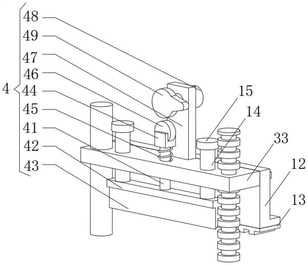
[0027] see Figure 1-3 , the present invention provides a technical solution: a shearing machine for hinge processing that is easy to maintain, including a base plate 1, a moving assembly 3, a shearing assembly 4 and a supporting assembly 5;

[0028] Bottom plate 1: the first belt conveyor 2 is installed on the right end of the upper side;

[0029] Mobile assembly 3: including installation frame 31, motor 32, moving block 33, threaded rod 34 and limit rod 35,...


PUM


Abstract

The invention discloses a convenient-to-maintain plate shearing machine for hinge machining. The convenient-to-maintain plate shearing machine comprises a bottom plate, a moving assembly, a shearing assembly and a supporting assembly. A first belt conveyor is mounted at the right end of the upper side surface of the bottom plate; the moving assembly comprises a mounting frame, a motor, a moving block, a threaded rod and a limiting rod, the mounting frame is fixed to the left end of the upper side face of the bottom plate, the left side of the first belt conveyor is fixed to the right side faceof the mounting frame, the motor is mounted on the upper side face of the mounting frame, the moving block is slidably connected into the mounting frame, a threaded hole is formed in the front side edge of the moving block, a threaded rod is in threaded connection with the interior of the threaded hole, adjustment can be conducted very conveniently, meanwhile, a plate can be fixed, the plate is prevented from deviating in the shearing process, manual placement can be avoided, and overhauling can be conducted very conveniently.

Description

technical field [0001] The invention relates to the technical field of shearing machines, in particular to a shearing machine for hinge processing which is convenient for maintenance. Background technique [0002] The plate shearing machine is a machine that uses one blade to make a reciprocating linear motion relative to the other blade to cut the plate. It uses the moving upper blade and the fixed lower blade to apply shear to metal plates of various thicknesses with a reasonable blade gap. The shearing machine belongs to a kind of forging machinery. When the existing shearing machine is placed, if there is a slight inclination, the support seat cannot be adjusted, resulting in the adjustment of the plate. Unqualified cut products will appear during shearing, and when placing the plate that needs to be cut, it needs to be placed manually. In this case, it is very easy to be dangerous. At the same time, the existing shearing machine is cutting the plate When the plate will...

Claims


Application Information

Patent Timeline
Patent Type & Authority Applications(China)
IPC IPC(8): B23D33/00B23D33/02B23D15/08
CPCB23D15/08B23D33/00B23D33/02
Inventor 刘帅
Owner 刘帅
Why Eureka
Try Eureka