

Portable iron sheet cutting machine
A cutting machine and iron sheet technology, applied in metal sawing equipment, sawing machine equipment, metal processing equipment, etc., can solve the problems of large floor space, leakage of blades, and troublesome handling, so as to achieve a small floor space and avoid injury. People, easy to carry effect
- Summary
- Abstract
- Description
- Claims
- Application Information
AI Technical Summary
Problems solved by technology
Method used
Image

Examples
Embodiment Construction
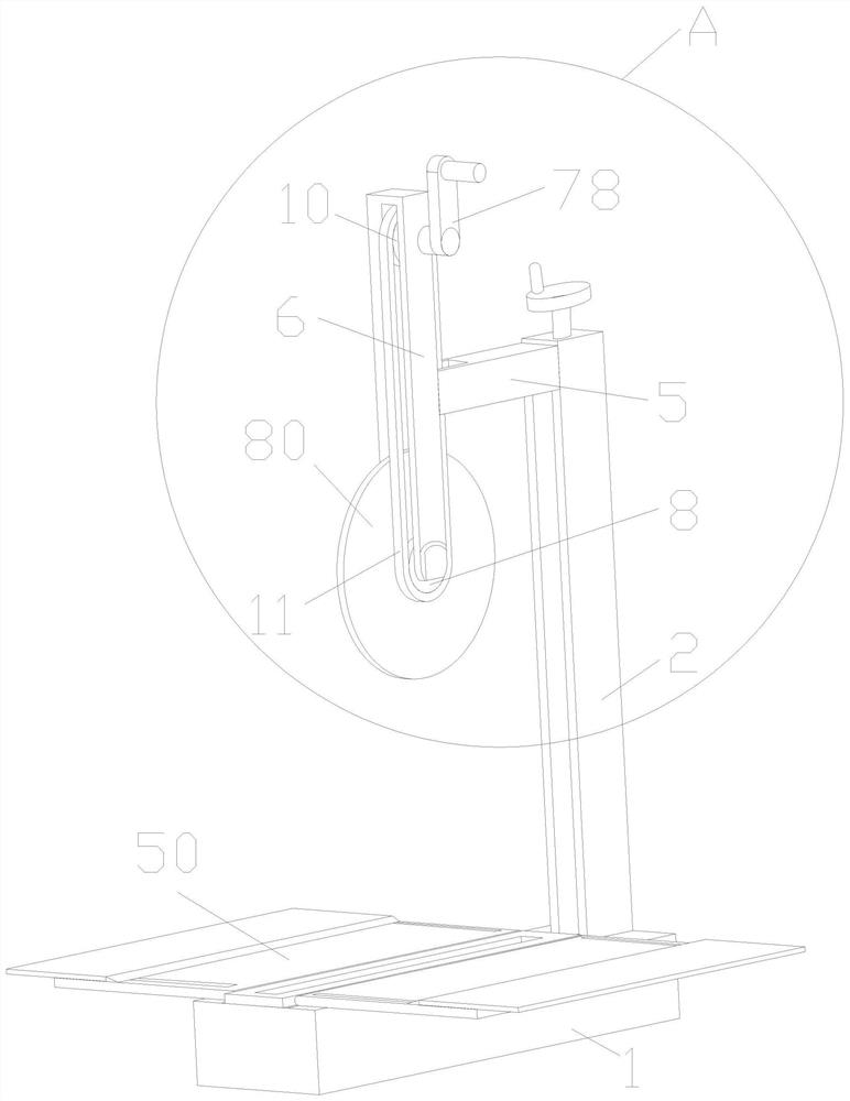
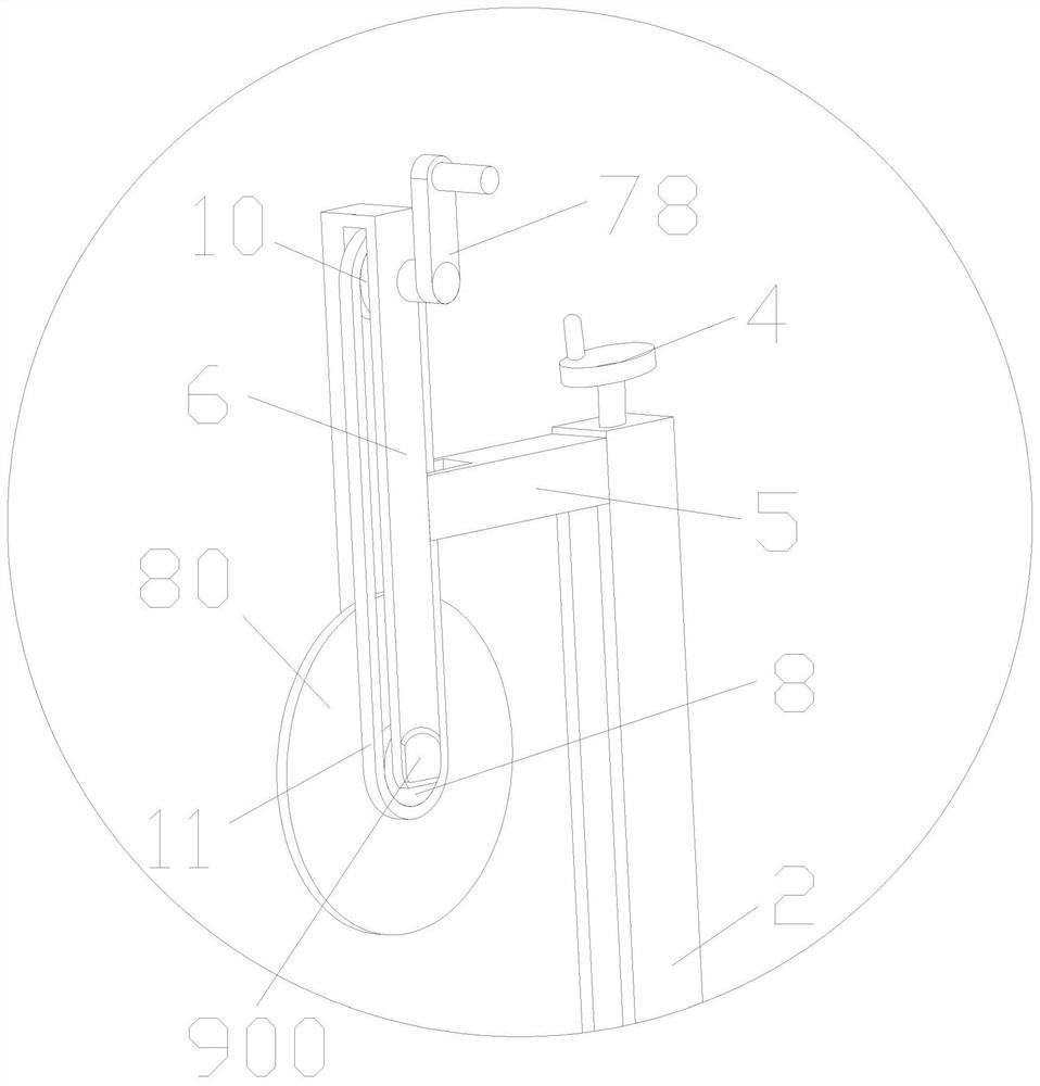
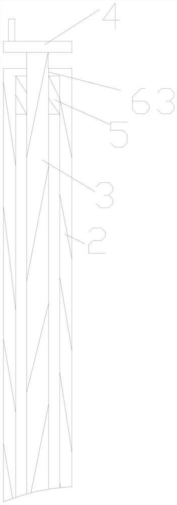
[0020] Such as Figure 1-8 As shown, a portable iron sheet cutting machine, a portable iron sheet cutting machine, includes a hollow seat 1, and is characterized in that: the feeding groove on the upper side of the inner wall of the hollow seat 1, the upper end of the hollow seat 1 A column 2 is fixedly arranged, and a movable groove is arranged on one side of the column 2, and a through hole 63 is arranged on the side wall of the movable groove away from the hollow seat 1, and a side wall of the movable groove is close to the hollow seat 1. A threaded rod 3 is rotated on the side wall, and one end of the threaded rod 3 close to the through hole 63 is fixedly provided with a first rotating handle 4, and a moving plate 5 is threaded on the threaded rod 3, and the moving plate 5 is away from One end of the column 2 is fixedly provided with a bracket 6, on which a first rotating shaft is rotated, on which a circular saw blade 80 is fixedly arranged, and on the first rotating shaf...
PUM
 Abstract
Description
Claims
Application Information