Supercharge Your Innovation With Domain-Expert AI Agents!

Wet dust removal cutting platform

A cutting platform, wet dust removal technology, applied in the direction of welding/cutting auxiliary equipment, auxiliary equipment, plasma welding equipment, etc., can solve a large amount of dust, debris, not suitable for vacuum cleaner dust removal, debris density and other problems, to achieve no noise Pollution and dust removal effects are stable and adaptable

Inactive Publication Date: 2021-01-12
浙江德宝通讯科技股份有限公司
View PDF7 Cites 0 Cited by
  • Summary
  • Abstract
  • Description
  • Claims
  • Application Information

AI Technical Summary

Problems solved by technology

When cutting, the material needs to be placed on the cutting platform, but when cutting, a lot of dust and debris will be generated, so it is necessary to perform dust removal on the workbench in time, because the cutting platform is usually a large plane and the cutting debris Usually dense so it is not suitable for dust removal by usual vacuum cleaners

Method used


Image

  • Wet dust removal cutting platform
  • Wet dust removal cutting platform
  • Wet dust removal cutting platform

Examples


Embodiment 1

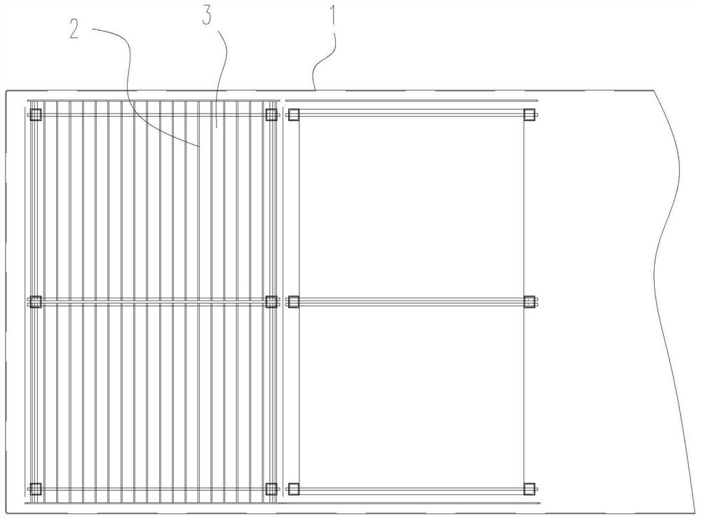
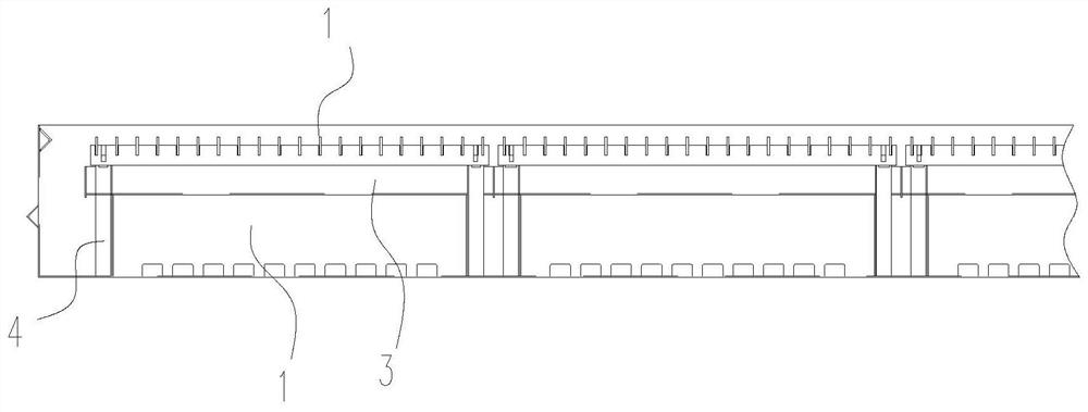
[0023] Such as figure 1 , 2 As shown, a wet dust removal cutting platform includes a water tank 1 and a cutting table located in the water tank. The cutting table is a grid surface, that is, a plane arranged at intervals by strip plates 2. Below the cutting table, there are The slag collecting pan 3, debris can fall into the slag collecting pan below from the gap between the strip plates. An air bag 4 is arranged in the water tank to control the water surface of the water tank to move up and down on the cutting table by controlling the size of the air bag, so as to clear the slag on the cutting table.

[0024] Multiple small wet dust removal cutting platforms are arranged to form a large wet dust removal cutting platform. The specific number of small wet dust removal cutting platforms can be determined according to needs. The lifting device of each small wet dust removal cutting platform is independently controlled, which is convenient for the position of dust removal as requ...

Embodiment 2

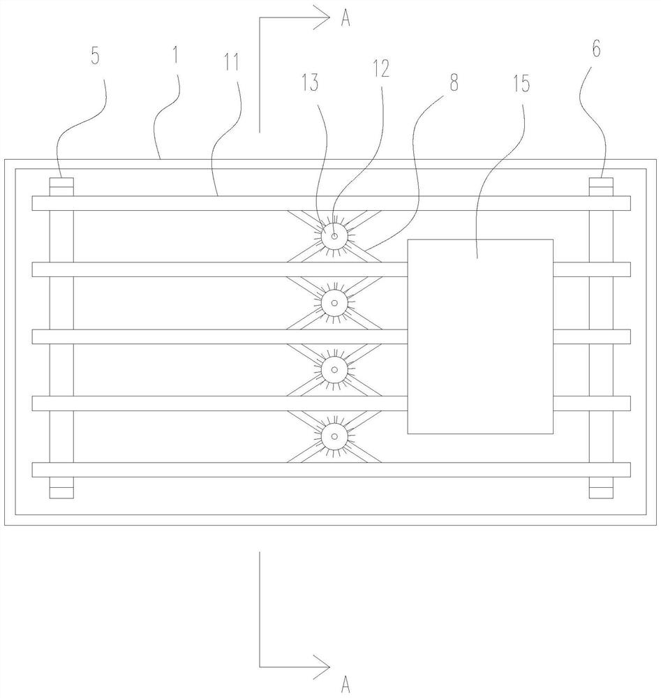
[0026] Such as image 3 , 4 As shown in . state. Lifting support can be controlled by cylinder 7.

[0027] The structure of the scissor deformation frame is arranged between the support rods is similar to the lifting mechanism of the scissor lift truck, that is, the scissor deformation frame is composed of a plurality of scissor units, and the scissor unit includes two rod bodies 8, two The middle of each rod body is connected by a middle hinge 9, and the rod body ends of two adjacent scissor units are connected by an end hinge 10.

[0028] The support rod is provided with a guide groove 111, and the end hinge of the scissors deformation frame is slidably fitted in the guide groove, and the height adjustment of the first lifting bracket and the second lowering bracket makes the support rod tilt As a result, the scissor deformation frame slides to one side, and the distance between the support rods can also be changed synchronously, so as to meet the requirements of workpie...


PUM


Abstract

The invention provides a wet dust removal cutting platform, and relates to a cutting platform with a dust removal function. The wet dust removal cutting platform solves the problem of dust removal ofa cutting platform in the prior art. The wet dust removal cutting platform comprises a water tank and a cutting table board located in the water tank. An air bag is arranged in the water tank. The water surface of the water tank is controlled to move up and down on the cutting table board by controlling the size of the air bag. The wet dust removal cutting platform is composed of the inflation anddeflation type air bag, a slag collecting disc, the external water tank, a grating plate and other assemblies. The wet dust removal cutting platform is mainly used for the cutting platform during plasma cutting of steel plates, the dust removal function is achieved, and the water surface can be rapidly lifted so that slag removal and workpiece collection can be facilitated. Due to the fact that the water surface is dynamically controllable, the water surface can be lifted according to needs so that the best dust removal effect can be achieved.

Description

technical field [0001] The invention belongs to the technical field of material cutting, in particular to a cutting platform with dust removal function. Background technique [0002] Material cutting is often required in industrial production, such as plasma cutting of metals. When cutting, the material needs to be placed on the cutting platform, but when cutting, a lot of dust and debris will be generated, so it is necessary to remove the dust from the workbench in time, because the cutting platform is usually a large plane and the cutting debris It is usually dense so it is not suitable for dust removal by ordinary vacuum cleaners. Contents of the invention [0003] The object of the present invention is to solve the above-mentioned problems in the prior art, and propose a wet dust removal cutting platform. The wet dust removal cutting platform utilizes the lifting and lowering of the cutting platform in water to remove dust. [0004] The purpose of the present inventi...

Claims


Application Information

Patent Timeline
IPC IPC(8): B23K10/00B23K37/00
CPCB23K10/00B23K37/00
Inventor 张平陈建明陈江棋陈永军徐养松
Owner 浙江德宝通讯科技股份有限公司
Features
  • R&D
  • Intellectual Property
  • Life Sciences
  • Materials
  • Tech Scout
  • Unparalleled Data Quality
  • Higher Quality Content
  • 60% Fewer Hallucinations
Learn More