Supercharge Your Innovation With Domain-Expert AI Agents!

Electric fan swing angle adjusting device

A technology for regulating devices and electric fans, which is applied to pump devices, non-variable pumps, machines/engines, etc., and can solve problems such as increasing the difficulty of compatible installation, production costs, and incompatibility

Inactive Publication Date: 2021-01-12
蒋亮健
View PDF1 Cites 0 Cited by
  • Summary
  • Abstract
  • Description
  • Claims
  • Application Information

AI Technical Summary

Problems solved by technology

[0002] In the prior art, there is a control technology based on changing the crank length with the movement of the planetary gear train to realize the swing angle adjustment of the electric fan (such as the invention technology of patent No. To disengage, control the pawl to disengage or withhold the driving gear by controlling the long side of the ratchet wheel, and manipulate the driving gear—the separation and combination of the pawl clutch device, so that the planetary gear and the sun gear have a relative angular displacement, and the length of the crank is changed, so as to achieve control The purpose of fan swing angle change, however, since the driving gear is the main reduction ratio transmission component in the reduction mechanism composed of worm-worm gear-worm shaft-driving gear, it is restricted by the parameters of the reduction ratio of the electric fan's shaking head. When the ratchet function of the clutch device is used, there are often problems of incompatibility with traditional electric fans, conflicts in the reduction ratio of the shaking head, and increase in position and volume space. cost, which needs to be improved

Method used


Image

  • Electric fan swing angle adjusting device
  • Electric fan swing angle adjusting device
  • Electric fan swing angle adjusting device

Examples


Embodiment Construction

[0009] The present invention will be further described below with embodiment and accompanying drawing:

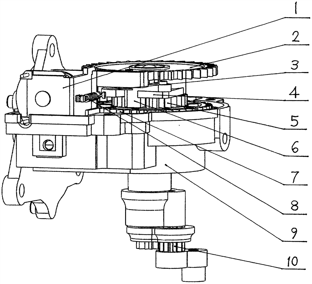
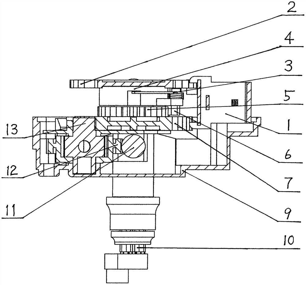
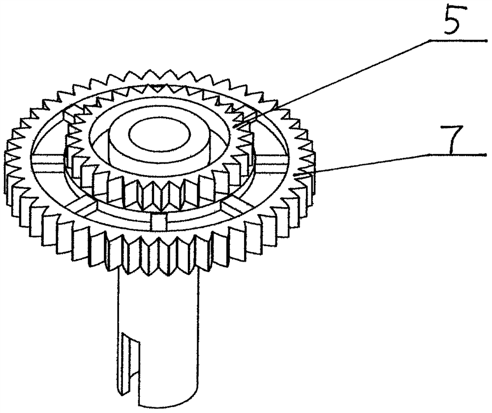
[0010] refer to figure 1 figure 2 and image 3 , the present invention includes a gearbox housing 9, a group of reduction mechanisms consisting of worm 11—worm gear 12—worm gear shaft 13—driving gear 7, and a set of variable angle mechanical devices composed of planetary gears 10 and variable length cranks. 1. A set of clutch control device and magnetic braking device 1 composed of pawl seat 4, pawl 6, return spring 3, control ratchet wheel 2, a ratchet wheel 5 is arranged concentrically between the driving gear 7 and the pawl seat 4, The size of the addendum circle of the ratchet 5 is smaller than that of the driving gear 7. The ratchet 5 and the driving gear 7 are produced in an integrated manner. The pawl seat 4 is equipped with a pawl 6 that is buckled on the ratchet 5 by the return spring 3 to form a set. The clutch device forms a group of electric fan swing angle ...


PUM


Abstract

The invention discloses an electric fan swing angle adjusting device. The device comprises a gear box shell, a speed reducing mechanism composed of a worm, a worm wheel, a worm wheel shaft and a driving gear, an angle changing mechanical device composed of a planetary gear train variable-length crank, a clutch control device composed of a pawl seat, a pawl, a reset spring and a control ratchet wheel, and a magnetic attraction braking device. The device is characterized in that a ratchet wheel with a small addendum circle is concentrically arranged between the driving gear and the pawl seat, the ratchet wheel and the driving gear are integrally produced and formed, and the pawl is buckled and pressed on the ratchet wheel through the reset spring to form a set of clutch device, so that a setof electric fan swing angle adjusting device which meets the requirement of the traditional electric fan swing reduction ratio parameter, and can meet the requirement that the clutch device is compact in size and compatible with a traditional electric fan motor head shell is formed.

Description

technical field [0001] The invention relates to an electric fan swing angle device, in particular to an electric fan swing angle adjustment device. Background technique [0002] In the prior art, there is a control technology based on changing the crank length with the movement of the planetary gear train to realize the swing angle adjustment of the electric fan (such as the invention technology of patent No. To disengage, control the pawl to disengage or withhold the driving gear by controlling the long side of the ratchet wheel, and manipulate the driving gear—the separation and combination of the pawl clutch device, so that the planetary gear and the sun gear have a relative angular displacement, and the length of the crank is changed, so as to achieve control The purpose of fan swing angle change, however, since the driving gear is the main reduction ratio transmission component in the reduction mechanism composed of worm-worm gear-worm shaft-driving gear, it is restrict...

Claims


Application Information

Patent Timeline
IPC IPC(8): F04D25/10
CPCF04D25/105
Inventor 蒋亮健
Owner 蒋亮健
Features
  • R&D
  • Intellectual Property
  • Life Sciences
  • Materials
  • Tech Scout
  • Unparalleled Data Quality
  • Higher Quality Content
  • 60% Fewer Hallucinations
Learn More