Mounting base for efficient illuminating lamp

A technology for mounting bases and lighting lamps, which is applied in the direction of lighting devices, lighting auxiliary devices, lighting device components, etc., and can solve the problems of high-efficiency lighting lamps not having self-adaptive cleaning, poor use of high-efficiency lighting lamps, and poor fit of mounting bases. Poor performance and other problems, achieve good application prospects, solve the effect of self-adaptive cleaning and small transmission torque

Active Publication Date: 2021-01-12
NANOLEAF ENERGY TECH SHENZHEN LTD
View PDF13 Cites 0 Cited by
  • Summary
  • Abstract
  • Description
  • Claims
  • Application Information

AI Technical Summary

Problems solved by technology

[0003] In the installation process of the existing high-efficiency lighting lamps, most of them are fixed installations; it is difficult to adjust the height adaptively; at the same time, the adaptability of the mounting bases of the existing high-efficiency lighting lamps during the installation process is relatively poor. Poor, because most of the high-efficiency lighting lamps do not have the function of self-adaptive cleaning during use, resulting in the poor effect of high-efficiency lighting lamps during use, and then a mounting seat for high-efficiency lighting lamps is proposed

Method used


Image

  • Mounting base for efficient illuminating lamp
  • Mounting base for efficient illuminating lamp
  • Mounting base for efficient illuminating lamp

Examples


Embodiment 1

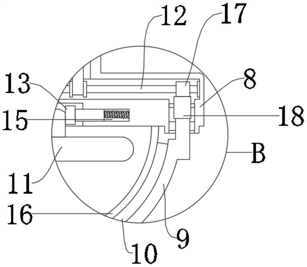
[0022] see Figure 1-4 , a mounting seat 8 for a high-efficiency lighting lamp, comprising a base plate 1, a box body 14 and a lamp body 11, wherein the base plate 1 and the wall are fixedly connected by bolts, and the box body 14 is fixedly connected to the base plate 1; A transfer assembly is arranged and installed in the box body 14, and a mounting seat 8 is connected and installed on the transfer assembly, and the lamp body 11 is arranged and installed on the mounting seat 8; further, on the mounting seat 8 A lampshade 16 is fixedly connected to the lampshade 16, and a cleaning device is installed on the outside of the lampshade 16, and the lampshade 16 is cleaned through the cleaning device; the actual lighting effect is further improved; wherein, the cleaning device and the transfer assembly The power connection between them further improves the actual utilization effect of the power of the transfer device.

[0023] Specifically, in this embodiment, the shape of the box...

Embodiment 2

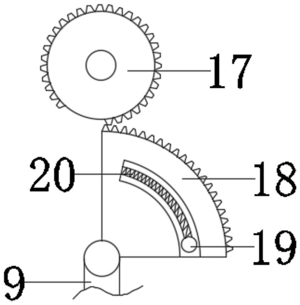
[0026] In order to further illustrate the cleaning device in the above embodiment, in another embodiment of the present invention, a mounting base 8 for a high-efficiency lighting lamp, the cleaning device includes a turntable, a cleaning strip 10 and a drive assembly; further , in this embodiment, the lampshade 16 is arranged in a semicircle, the turret 9 is rotatably mounted on the mounting base 8, the cleaning strip 10 is fixedly connected to the turret 9, and is attached to the surface of the lampshade 16; One end of the above-mentioned turret 9 is connected with the motor 7 through the driving assembly, further realizing the rotation of the turret 9 along the surface of the lampshade 16; realizing the cleaning of the lampshade 16.

[0027] Specifically, the drive assembly includes a rotating rod 12, a driving wheel 17 and a driving block 18, wherein the rotating rod 12 is rotatably mounted on the mounting base 8, and is connected to the rotating shaft of the motor 7 throug...

Embodiment 3

[0029] In this embodiment, in order to further improve the actual use effect of the device, this embodiment has made the following improvements on the basis of the above embodiments. The improvement is that a slide rail is fixedly connected to the side of the chute 3 21. The movable box 4 and the sliding rail 21 are slip-fitted and installed to further improve the stability of the rotating box during the sliding process and reduce the radial load of the transfer screw 2.

[0030] Secondly, a movable groove 15 is symmetrically opened on the mounting seat 8, and an extruding block 13 is slidably installed in the movable groove 15, and a thrust spring is arranged between the extruding block 13 and the bottom of the movable groove 15. Further, in the thrust Under the action of the spring, the lamp body 11 is clamped between the extruding blocks 13 , which further enables the lamp body 11 to be quickly installed and has good adaptability.

[0031] According to the specific descript...


PUM


Abstract

The invention discloses a mounting base for an efficient illuminating lamp. The mounting base comprises a bottom plate, a box body and a lamp body. The box body is fixedly connected to the bottom plate. A transferring assembly is arranged in the box body, a mounting base body is connected to the transferring assembly, and the lamp body is arranged on the mounting base body. A lampshade is fixedlyconnected to the mounting base body, a cleaning device is arranged on the outer side of the lampshade, and the cleaning device is in power connection with the transferring assembly. The mounting basefor the efficient illuminating lamp is simple in mechanism, reasonable and high in practicability; a movable box is driven to move through transmission of a transferring lead screw, the beneficial effects of being small in transmission torque, accurate in transmission and capable of saving labor are achieved, the motor load is reduced, meanwhile, a motor further drives a rotating frame to rotate to achieve reciprocating motion of the rotating frame, cleaning of the outer side of the lampshade is achieved, the motor utilization rate is effectively increased, and meanwhile, the problems that theprior mounting base is not easy to move and self-adaptively clean are solved; and good application prospects are realized.

Description

technical field [0001] The invention relates to the field of energy-saving lamps, in particular to a mounting base for high-efficiency lighting lamps. Background technique [0002] High-efficiency energy-saving lamps have the characteristics of high brightness, no color difference, stable light effect, and energy saving and money saving. It not only saves 60% to 80% of electricity than ordinary lamps, but also has a service life of four to six times longer. It has the characteristics of fast start, no flicker, no power frequency noise, low temperature rise, and long life. It is especially suitable for energy-saving and environmental protection renovation of various large lighting places such as shopping malls, factories, schools, hospitals, etc. [0003] In the installation process of the existing high-efficiency lighting lamps, most of them are fixed installations; it is difficult to adjust the height adaptively; at the same time, the adaptability of the mounting bases of ...

Claims


Application Information

Patent Timeline
IPC IPC(8): F21V21/34B08B1/00B08B13/00
CPCF21V21/34B08B13/00B08B1/10
Inventor 陈小慧
Owner NANOLEAF ENERGY TECH SHENZHEN LTD
Why Eureka
Try Eureka