Ventilation energy-saving system of green building

A green building and energy-saving system technology, applied in ventilation systems, space heating and ventilation details, space heating and ventilation, etc., can solve problems such as inconvenient use of equipment, reduced indoor ventilation efficiency, increased ventilation costs, etc., to achieve structural simple effect

Inactive Publication Date: 2021-01-12
王涛
View PDF5 Cites 0 Cited by
  • Summary
  • Abstract
  • Description
  • Claims
  • Application Information

AI Technical Summary

Problems solved by technology

[0002] There are many shortcomings in the existing ventilation equipment. Most of the general ventilation equipment are installed in the wall. However, when the glass windows in some high-rise areas cannot be effectively opened, ventilation is required at this time. In most cases, only Open the window obliquely for ventilation. The main problem is that the window can only be opened at a certain angle for efficient ventilation, and it is impossible to use the fan structure to ventilate the air against the opened window, so that the efficiency of indoor ventilation is extremely high. Due to the existence of the above shortcomings, the actual ventilation efficiency of the equipment is reduced, and the convenience of opening or closing the equipment is not high, and the combination of the fan and the normal ventilation cannot be realized. Ventilation with the help of existing ventilation equipment can only be achieved by setting up ventilation equipment on the wall. It is precisely because of the above shortcomings that not only increases the cost of ventilation, but also makes it inconvenient for personnel to use the equipment.

Method used


Image

  • Ventilation energy-saving system of green building
  • Ventilation energy-saving system of green building
  • Ventilation energy-saving system of green building

Examples


Embodiment Construction

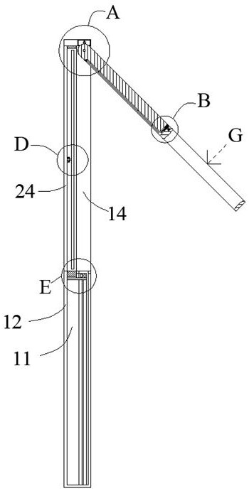
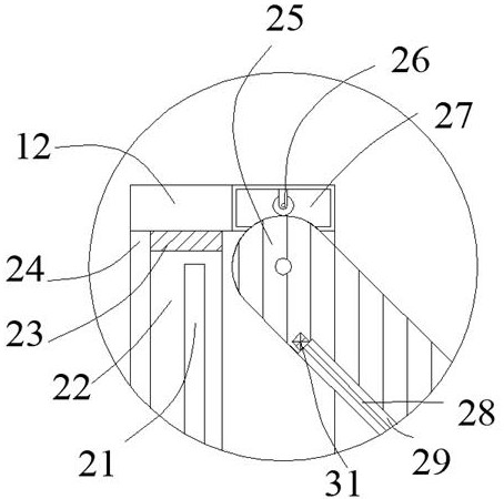
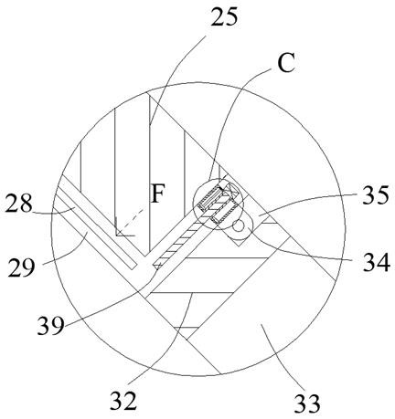
[0026] Such as Figure 1-Figure 10 As shown, the present invention is described in detail. For the convenience of description, the orientations mentioned below are now stipulated as follows: figure 1 The up, down, left, right, front and back directions of the projection relationship are consistent. A ventilation and energy-saving system for green buildings of the present invention includes a bottom box body 12, and a sliding hole 11 is arranged in the bottom box body 12, and one side of the sliding hole 11 is connected to each other. There is a connection cavity 14, the sliding hole 11 is provided with a fan ventilation device that can be lifted and lowered to ventilate with the outside world, the bottom box 12 is provided with an internal cavity 27, and the internal cavity 27 is provided with a motor-driven Engaging driving gear 26, a swing plate 25 is hingedly arranged in the connecting cavity 14, and the swinging plate 25 is engaged with the engaging driving gear 26, and on...


PUM


Abstract

The invention discloses a ventilation energy-saving system of a green building. The system comprises a bottom box body, a sliding hole is formed in the bottom box body, a connecting cavity is formed at one side of the sliding hole in a communicating manner, a fan ventilation device capable of being ventilated with the outside after ascending and descending is arranged in the sliding hole, and an inner containing cavity is formed in the bottom box body. A meshing driving gear driven by a motor is arranged in the inner containing cavity, a swing plate is hinged into the connecting cavity, the swing plate is meshed with the meshing driving gear, and a connecting side box body is arranged at one side of the swing plate; and an adjusting device enabling the connecting side box body to be flushwith the swing plate and to be folded at one side of the swing plate is arranged between the swing plate and the connecting side box body, ventilation can be conducted after the system is started, windows can be overlapped to facilitate ventilation, and ventilation can be conducted by means of a fan in an external space.

Description

technical field [0001] The invention relates to the technical field of ventilation equipment, in particular to a ventilation and energy-saving system for green buildings. Background technique [0002] There are many shortcomings in the existing ventilation equipment. Most of the general ventilation equipment are installed in the wall. However, when the glass windows in some high-rise areas cannot be effectively opened, ventilation is required at this time. In most cases, only Open the window obliquely for ventilation. The main problem is that the window can only be opened at a certain angle for efficient ventilation, and it is impossible to use the fan structure to ventilate the air against the opened window, so that the efficiency of indoor ventilation is extremely high. Due to the existence of the above shortcomings, the actual ventilation efficiency of the equipment is reduced, and the convenience of opening or closing the equipment is not high, and the combination of the...

Claims


Application Information

Patent Timeline
IPC IPC(8): F24F7/013F24F13/00F04D25/08
CPCF04D25/08F24F7/013F24F13/00
Inventor 王涛
Owner 王涛
Why Eureka
Try Eureka