Multifunctional hyperelastic film biaxial tension test bench
A biaxial stretching and superelasticity technology, applied in the direction of applying stable tension/pressure to test material strength, strength characteristics, measuring devices, etc., can solve the problems affecting test accuracy, sample edge and corner distortion, and high detection , to achieve the effect of improving test accuracy, preventing loosening, and reducing manufacturing and installation errors
- Summary
- Abstract
- Description
- Claims
- Application Information
AI Technical Summary
Problems solved by technology
Method used
Image
Examples
Embodiment 1
[0038] It should be noted that if there is a directional indication (such as up, down, left, right, front, back...) in the embodiment of the present invention, it is only used to explain the relationship between the components in a certain posture. If the specific posture changes, the directional indication will also change accordingly.
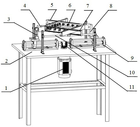
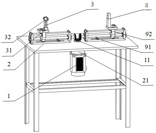
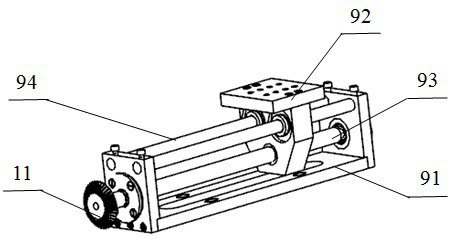
[0039] A multi-functional superelastic film biaxial tensile test bench, including a workbench 2, a force sensor 3, a screw nut mechanism 9, a driving mechanism for driving the screw nut mechanism 9 to rotate, and a telescoping mechanism driven by the screw nut mechanism 9 Telescopic mechanism, angle adjustment mechanism 4 for adjusting the angle of telescopic mechanism and clamping mechanism for clamping elastic film,
[0040]The driving mechanism, the lead screw nut mechanism 9 and the slideway bracket 10 are fixedly arranged on the workbench 2, the telescopic mechanism is slidably connected to the slideway support 10, the angle adjustment m...
Embodiment 2
[0069] The difference from Embodiment 1 is that in this embodiment, the right angle included angle of the inner slideway 5 is fixedly arranged on the right angle adjustment mechanism, the right angle included angle of the outer slideway 7 is fixedly arranged on the left angle adjustment mechanism, and the force sensor 3 The sensor support 31 is fixedly installed on the left slide part, the upper end of the force sensor 3 is fixedly connected to the left angle adjustment mechanism through the sensor connection block 32, and the right angle adjustment mechanism is fixedly installed on the right slide part through the L-shaped bracket 8.
Embodiment 3
[0071] The difference from Embodiment 1 is that in this embodiment, the right angle included angle of the inner slideway 5 is fixedly arranged on the left angle adjustment mechanism, the right angle included angle of the outer slideway 7 is fixedly arranged on the right angle adjustment mechanism, and the force sensor 3 The sensor support 31 is fixedly installed on the right slide part, the upper end of the force sensor 3 is fixedly connected to the right angle adjustment mechanism through the sensor connection block 32, and the left angle adjustment mechanism is fixedly installed on the left slide part through the L-shaped bracket 8.
PUM
 Abstract
Description
Claims
Application Information
 - R&D
- Intellectual Property
- Life Sciences
- Materials
- Tech Scout
- Unparalleled Data Quality
- Higher Quality Content
- 60% Fewer Hallucinations
Browse by: Latest US Patents, China's latest patents, Technical Efficacy Thesaurus, Application Domain, Technology Topic, Popular Technical Reports.
© 2025 PatSnap. All rights reserved.Legal|Privacy policy|Modern Slavery Act Transparency Statement|Sitemap|About US| Contact US: help@patsnap.com


