
Vibration-assisted nano rolling device

A vibrating device and rolling technology, applied in the field of hot embossing, can solve the problems of obstructing ultrasonic waves, low filling rate, pattern damage accuracy, etc., and achieve the effects of improving filling degree, uniform force and eliminating air bubbles.

Pending Publication Date: 2021-01-12
CHANGCHUN UNIV OF TECH
View PDF1 Cites 0 Cited by
  • Summary
  • Abstract
  • Description
  • Claims
  • Application Information

AI Technical Summary

Problems solved by technology

However, the finished imprinted products have defects such as low filling rate, broken patterns and poor precision. In order to solve these defects, researchers have transferred the research field to ultrasonic vibration-assisted imprinting.
[0003] In the patent with the publication number CN 102336016 A, the Japanese scholar H. Mekaru and the Korean scholar Hyun Woo Yu all proposed the method of ultrasonic assisted imprinting. The heat generated by ultrasonic vibration is concentrated on the contact interface between the mold and the embossing rubber, causing most of the The embossing glue is not heated, but only a very small part is melted, thereby improving the heat shrinkage after the embossing glue is formed, and the ultrasonic vibration assists the embossing process, the ultrasonic vibration is on the embossing glue and the raised part of the mold due to Friction is quickly converted into heat, which melts the imprinting glue, fills the mold gap, improves the filling degree of the imprinting glue, and obtains a micro-nano pattern with high precision. However, after the ultrasonic vibration is assisted, there will be residual Bubbles, and ultrasonic vibration has a better imprinting effect at low pressure, because high pressure will hinder the generation of ultrasonic waves, thereby affecting its imprinting effect

Method used


Image

  • Vibration-assisted nano rolling device
  • Vibration-assisted nano rolling device
  • Vibration-assisted nano rolling device

Examples


Embodiment Construction

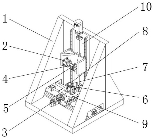
[0027] like figure 1 As shown, the vibration-assisted nano-rolling device includes a frame 1, a four-column connecting frame 2, a Z-direction vibration device 3, an embossing device 4, a fine-tuning device 5, a heating device 6, and a substrate chuck 7 , Cooling device 8, X-Y axis displacement platform 9, Z-axis displacement platform 10, wherein frame 1 is placed horizontally on the horizontal plane, Z-axis displacement platform 10 and X-Y axis displacement platform 9 are fixed on the frame 1 by screws, and the four-column connecting frame 2 is fixed on the Z-axis displacement platform 10 by screws, the imprinting device 4 is fixed on the four-column connecting frame 2 by screws, the Z-direction vibration device 3 is fixed on the X-Y axis displacement platform 9 by screws, and the heating device 6 is fixed on the Z-axis by screws. On the vibration device 3, the substrate chuck 7 is fixed on the heating device 6 by screws, the height of the placed substrate is higher than the d...


PUM


Abstract

The invention relates to a vibration-assisted nano rolling device, which comprises the following steps that firstly, a rack is horizontally placed on an experiment table, then an X-Y-axis displacementplatform is adjusted to enable a Z-direction vibration device to be positioned right below an imprinting roller, a glued substrate is fixed in the center of a substrate chuck, a fine adjustment device is adjusted to enable the imprinting roller to be horizontal, and then the Z-axis displacement platform is controlled to move downwards to enable the imprinting roller to be in micro contact with the imprinting glue, the heating device is started to heat the substrate, imprinting is started after heating is completed, the Z-direction vibration device starts to vibrate while imprinting is conducted, then cooling and demolding are conducted, and finally the Z-axis displacement platform is controlled to ascend, and imprinting is completed. The Z-direction vibration device is adopted, so that gap contact is generated between the template and the imprinting glue, the adhesive force between the template and the imprinting glue is reduced, friction heat production is performed through multipletimes of gap contact, the imprinting glue melts and flows, the filling degree of the imprinting glue is improved, the imprinting roller is adjusted to be horizontal through the fine adjustment device,and the cooling device is used for cooling; and the precision and fidelity of the micro-nano structure are further improved.

Description

technical field [0001] The invention relates to the field of thermal embossing, in particular to a vibration-assisted nano-rolling device. Background technique [0002] Nanoimprint technology has the advantages of low cost, high resolution, and mass production, and is widely used in optical lenses, self-cleaning, and microelectronics manufacturing processes. It has attracted the general attention and research enthusiasm of researchers in the industry. MIT Technology Review will It is listed as one of the top ten emerging technologies that will change the world. However, the finished imprinted products now have defects such as low filling rate, pattern damage and poor precision. In order to solve these defects, researchers shifted their research field to ultrasonic vibration-assisted imprinting. [0003] In the patent with the publication number CN 102336016 A, the Japanese scholar H. Mekaru and the Korean scholar Hyun Woo Yu all proposed the method of ultrasonic assisted im...

Claims


Application Information

Patent Timeline
IPC IPC(8): G03F7/00
CPCG03F7/0002
Inventor 谷岩林洁琼康洺硕张昭杰陈斯易正发徐贞潘李先耀颜家瑄徐宏宇冯开拓戴得恩刘骜卢发祥段星鑫
Owner CHANGCHUN UNIV OF TECH
Learn More