Fuel tank capable of achieving precise air-dropping and application method of fuel tank

An oil tank, precise technology, applied in container handles, containers, cans/barrels/barrels, etc., can solve the problems of low efficiency, inaccessibility, long transportation distance of large oil transportation vehicles, etc., to ensure effectiveness, avoid injury, high The effect of strength combined with mechanical properties

Pending Publication Date: 2019-09-10
HEBEI KELI AUTOMOBILE EQUIP CO LTD
View PDF2 Cites 1 Cited by
  • Summary
  • Abstract
  • Description
  • Claims
  • Application Information

AI Technical Summary

Problems solved by technology

[0003] Based on the all-weather and complexity of modern warfare, in many occasions, the distribution and supply of fuel for the last mile has become the key to the success or failure of the war, such as mountainous, forest, and sea operations. Large-scale oil transport vehicles have long transportation distances, low efficiency, and even cannot reach

Method used


Image

  • Fuel tank capable of achieving precise air-dropping and application method of fuel tank
  • Fuel tank capable of achieving precise air-dropping and application method of fuel tank
  • Fuel tank capable of achieving precise air-dropping and application method of fuel tank

Examples


Embodiment 1

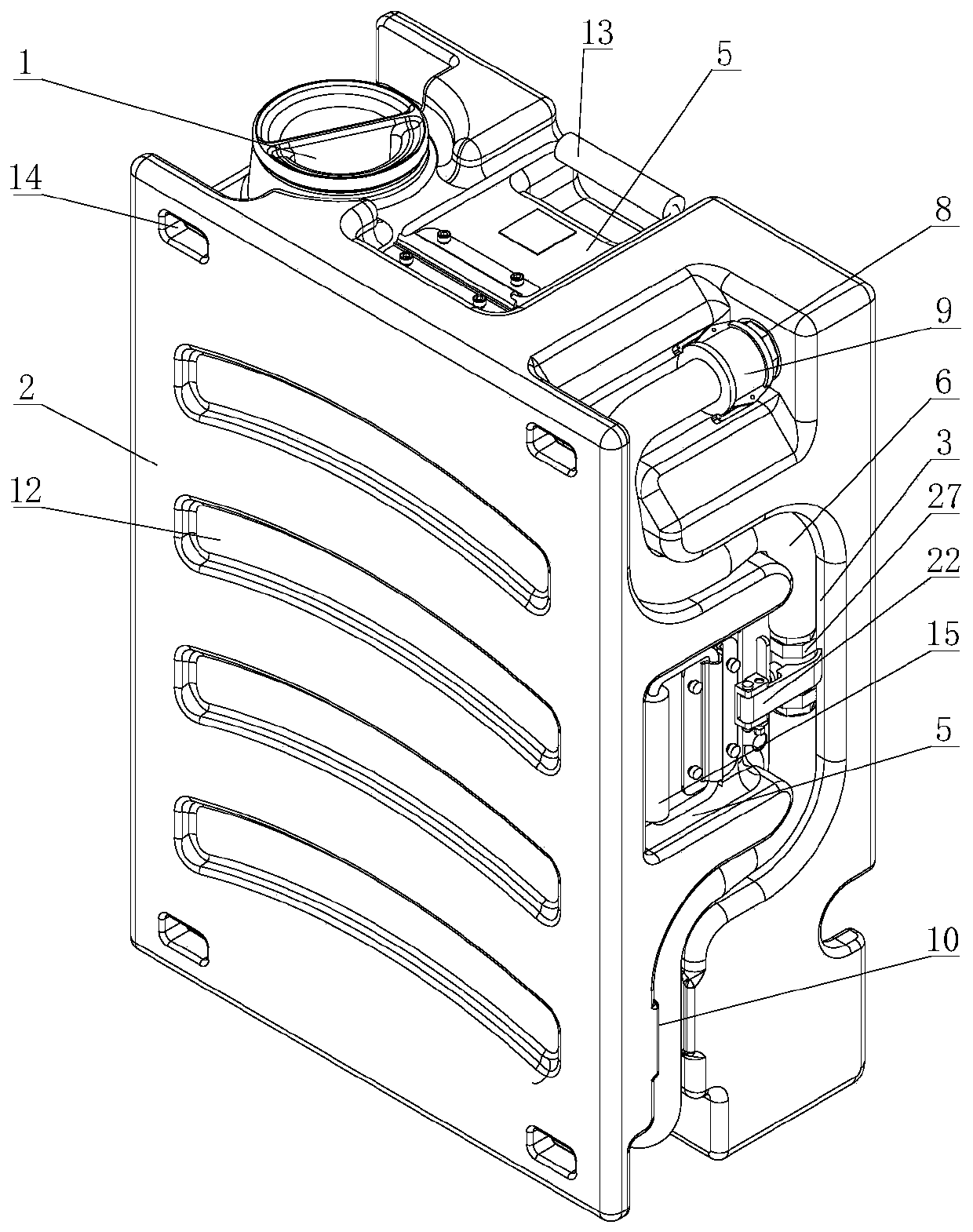
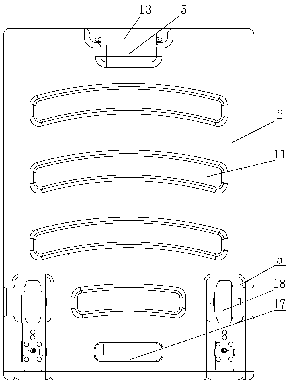
[0045] Example 1, such as Figure 1-14 As shown, the fuel injection port 1 is provided with a fuel tank cover 32, the front and rear sides of the box body 2 are respectively provided with a set of mutually matched stacking positioning ribs 11, stacking positioning concave ribs 12, stacking positioning convex The ribs 11 cooperate with the stacking positioning concave ribs 12 to form a stacking limiting structure of adjacent boxes 2. The stacking positioning convex ribs 11 and the stacking positioning concave ribs 12 between adjacent two boxes 2 can improve storage and The stacking stability of the box 2 during transportation; the box adopts a rectangular flat shape and a regular appearance structure, which can facilitate flexible and diverse stacking, storage and transportation, and can effectively improve the storage and transportation space utilization.

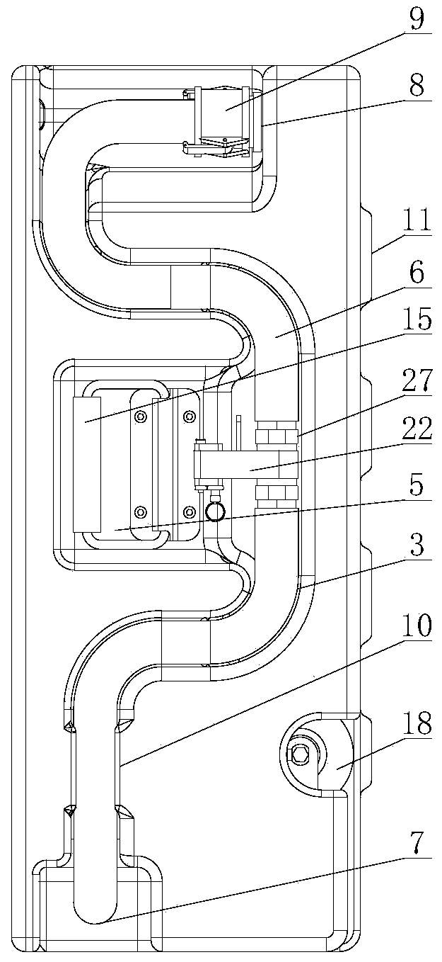
[0046] The first through opening 7 and the second through opening 8 are respectively provided at a set of diagonally opposit...

Embodiment 2

[0141] Example 2 is basically the same as Example 1, such as Figure 15 As shown, the difference is that the box 2 is also provided with an automatic force output unit and a second groove 4 for embedding the automatic force output unit. The second groove 4 and the automatic force output unit are located in the box 2 On the left, the automatic force output unit includes a compressed gas cylinder 30 arranged in the second groove 4 by means of a fixing plate 29, the compressed gas cylinder 30 is arranged vertically upwards, and the air outlet of the compressed gas cylinder 30 is connected to the box 2 The upper end is connected, and the upper part of the compressed gas cylinder 30 is provided with a knob. When the oil needs to be drained outwards, the upper port of the quick connection pipe 6 is connected with the equipment to be supplied, and the knob is rotated, and the compressed gas cylinder 30 is removed from the box 2 The upper end inputs compressed air into the tank 2, under...


PUM


Abstract

The invention relates to a fuel tank capable of achieving precise air-dropping, and belongs to the technical field of military equipment. The fuel tank comprises a tank body with a fuel injection opening formed in the top and a carrying unit arranged on the tank body. A reinforcement groove is formed in the tank body and comprises a first groove and a third groove used for containing the carryingunit. A centralized filling assembly is arranged in the first groove in an embedded manner and comprises a rapid connecting pipeline, a first through opening arranged on the tank body and matched withthe rapid connecting pipeline, a second through opening and a locating unit of the rapid connecting pipeline. A lower opening of the rapid connecting pipeline is connected with the first through opening, and an upper opening of the rapid connecting pipeline is connected with the second through opening through a rapid connecting unit. The fuel tank can meet the requirements of hoisting and air-dropping of unmanned aerial vehicles and helicopters in all-weather, all-terrain and multifunctional manners, and rapid and precise supply to mechanical equipment can be achieved.

Description

Technical field [0001] The invention belongs to the technical field of military equipment, and relates to a fuel tank, in particular to a fuel tank that can be accurately airdropped and a use method thereof. Background technique [0002] Military equipment and weapons are equally important, and are directly related to the success or failure of war. Through the timely application of new technologies and new materials that are constantly emerging to military equipment, it is used to improve the technical and tactical level of our military's military equipment, and then maintain the technical advantages of our military's military equipment. The work is of great significance. [0003] Due to the all-weather and complication of modern warfare, in many occasions, the delivery and supply of fuel for the last mile has become the key to the success or failure of wars, such as mountain, forest, and maritime operations. Large fuel transportation vehicles have long transportation distances, lo...

Claims


Application Information

Patent Timeline
Patent Type & Authority Applications(China)
IPC IPC(8): B65D1/20B65D1/42B65D25/28B65D25/24B65D21/028B65D21/036B67D7/78B67D7/72
CPCB65D1/20B65D1/42B65D21/0204B65D21/023B65D25/24B65D25/28B67D7/72B67D7/78
Inventor 张万武岳猛超
Owner HEBEI KELI AUTOMOBILE EQUIP CO LTD
Why Eureka
Try Eureka