Pin position design method and system, terminal and storage medium

A design method and pin technology, applied in computer-aided design, calculation, special data processing applications, etc., can solve the problems of time-consuming and labor-intensive, long time-consuming, increase the design schedule, etc., to achieve a wide range of application prospects, structure Simple, reliable design principles

Inactive Publication Date: 2021-01-12
SUZHOU LANGCHAO INTELLIGENT TECH CO LTD
View PDF0 Cites 0 Cited by
  • Summary
  • Abstract
  • Description
  • Claims
  • Application Information

AI Technical Summary

Problems solved by technology

[0005] When creating or modifying the schematic diagram, when encountering a design with a large number of Pins or a more complicated placement method, each PIN needs to be placed according to the requirements of EE, which takes a long time and may cause manual placement. In the case of wrong placement, hardware engineers need to modify it again through component design engineers when they draw circuit diagrams, which is time-consuming and labor-intensive and increases the entire design time.

Method used


Image

  • Pin position design method and system, terminal and storage medium
  • Pin position design method and system, terminal and storage medium
  • Pin position design method and system, terminal and storage medium

Examples


Embodiment Construction

[0045] In order to enable those skilled in the art to better understand the technical solutions in the present invention, the technical solutions in the embodiments of the present invention will be clearly and completely described below in conjunction with the drawings in the embodiments of the present invention. Obviously, the described The embodiments are only some of the embodiments of the present invention, not all of them. Based on the embodiments of the present invention, all other embodiments obtained by persons of ordinary skill in the art without making creative efforts shall fall within the protection scope of the present invention.

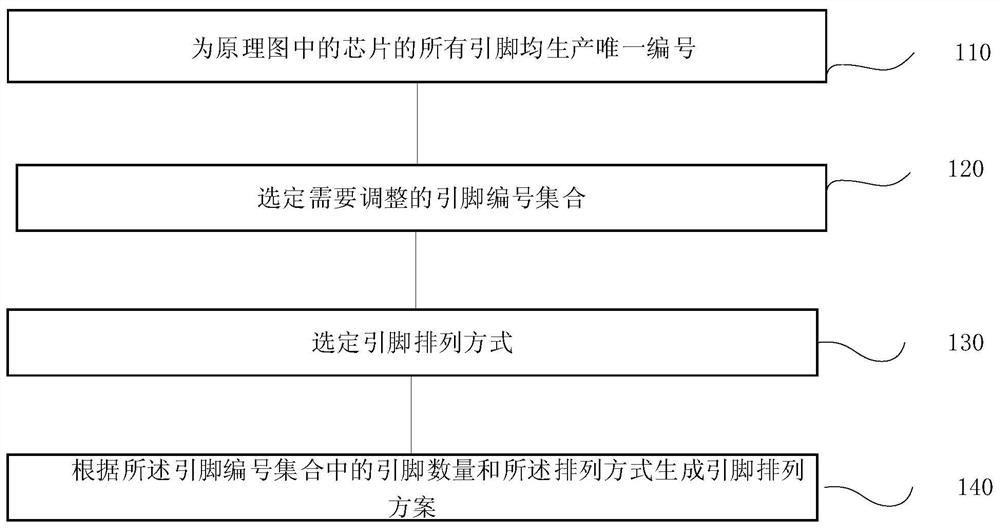
[0046] figure 1 is a schematic flowchart of a method in one embodiment of the present invention. in, figure 1 The executive body can design the system for one pin position.

[0047] Such as figure 1 As shown, the method includes:

[0048] Step 110, producing unique numbers for all pins of the chip in the schematic diagram;

[0049...


PUM


Abstract

The invention provides a pin position design method and system, a terminal and a storage medium. The pin position design method comprises the steps: generating a unique number for all pins of a chip in a schematic diagram; selecting a pin number set needing to be adjusted; selecting a pin arrangement mode; generating a pin arrangement scheme according to the number of the pins in the pin number set and the arrangement mode. The method is suitable for SYMBOL design of schematic diagrams of various types and large PIN numbers, greatly reduces manual single signal placement errors and naked eye recognition errors, omits manual repeated confirmation and modification through simple design, increases the speed, reduces errors and can be widely applied to schematic diagram design.

Description

technical field [0001] The invention relates to the technical field of circuit schematic design, in particular to a pin position design method, system, terminal and storage medium. Background technique [0002] The symbol drawn by the Concept Tool is called a schematic diagram. The schematic diagram is the basis of the circuit diagram. The entire circuit diagram is connected through a single schematic diagram. It is necessary to draw a single schematic diagram to ensure For its correctness and completeness, EE grabs a single schematic diagram from the public database and draws a complete circuit diagram. [0003] The design style of the schematic diagram will vary due to the type of parts or requirements, and it is common to have multiple PINs or complex placement methods. Therefore, in the process of server development, whether it is the first drawing of the schematic diagram or the modification of the circuit design to meet customer needs The demand is inevitable, whether...

Claims


Application Information

Patent Timeline
IPC IPC(8): G06F30/392
CPCG06F30/392
Inventor 许絲婷
Owner SUZHOU LANGCHAO INTELLIGENT TECH CO LTD
Why Eureka
Try Eureka