Supercharge Your Innovation With Domain-Expert AI Agents!

Wafer test circuit unit and method, wafer test circuit and wafer

A wafer test and circuit unit technology, applied in the wafer test circuit unit, wafer test circuit, and wafer field, can solve problems such as abnormal chip operation, and achieve the effect of solving abnormal chip operation

Pending Publication Date: 2021-01-12
CHANGXIN MEMORY TECH INC
View PDF0 Cites 0 Cited by
  • Summary
  • Abstract
  • Description
  • Claims
  • Application Information

AI Technical Summary

Problems solved by technology

[0005] The purpose of the present disclosure is to provide a wafer test circuit unit and method, a wafer test circuit, and a wafer, and then to a certain extent solve the problem of abnormal operation of the chip due to external parasitic resistance of the crystal grain in the related art

Method used


Image

  • Wafer test circuit unit and method, wafer test circuit and wafer
  • Wafer test circuit unit and method, wafer test circuit and wafer
  • Wafer test circuit unit and method, wafer test circuit and wafer

Examples


Embodiment Construction

[0061]Example embodiments will now be described more fully with reference to the accompanying drawings. Example embodiments may, however, be embodied in many forms and should not be construed as limited to the embodiments set forth herein; rather, these embodiments are provided so that this disclosure will be thorough and complete, and will fully convey the concept of example embodiments to those skilled in the art. The same reference numerals denote the same or similar parts in the drawings, and thus their repeated descriptions will be omitted.

[0062] Furthermore, the described features, structures, or characteristics may be combined in any suitable manner in one or more embodiments. In the following description, numerous specific details are provided in order to give a thorough understanding of embodiments of the present disclosure. However, those skilled in the art will appreciate that the technical solutions of the present disclosure may be practiced without one or mor...


PUM


Abstract

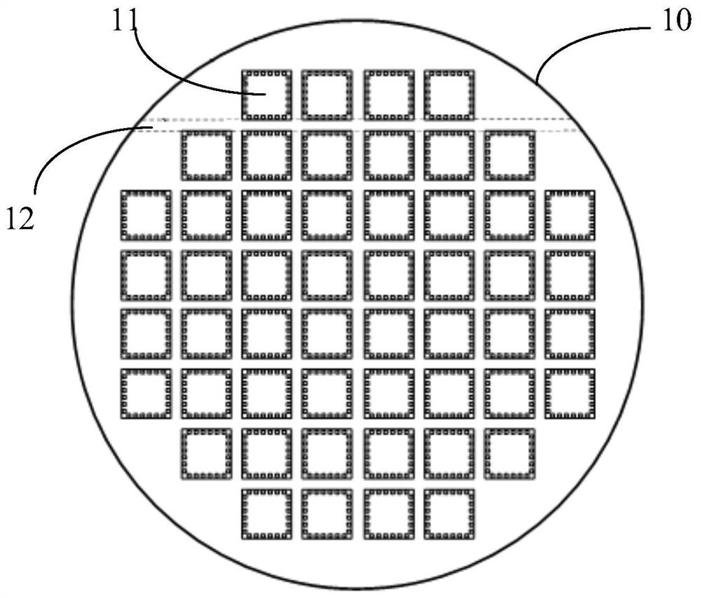
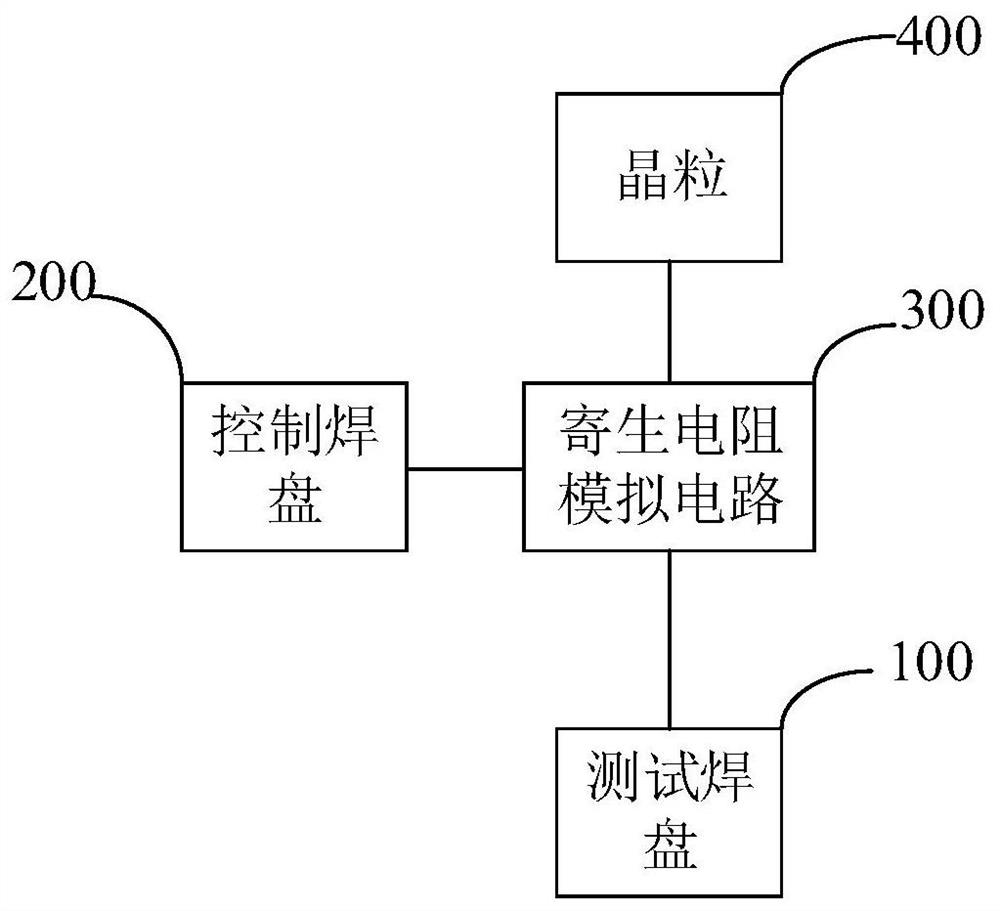
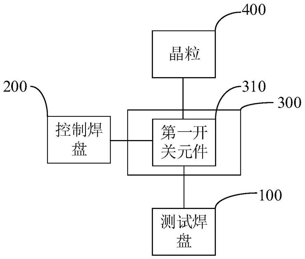
The invention relates to a wafer test circuit unit and method, a wafer test circuit and a wafer, the wafer test circuit unit is used for wafer test, the wafer comprises a crystal grain area and a scribing channel, the crystal grain area comprises at least one crystal grain, and the wafer test circuit unit comprises a test bonding pad, a control bonding pad and a parasitic resistance simulation circuit; the test bonding pad is arranged on the scribing channel and is used for inputting a test signal; the control bonding pad is arranged on the scribing channel and is used for inputting a controlsignal; and the parasitic resistance simulation circuit is connected with the test bonding pad, the control bonding pad and the crystal grain respectively, and is used for simulating the parasitic resistance outside the crystal grain and transmitting the test signal to the crystal grain in response to the control signal.

Description

technical field [0001] The present disclosure relates to the technical field of semiconductors, in particular, to a wafer testing circuit unit and method, a wafer testing circuit, and a wafer. Background technique [0002] With the development and progress of technology, chips are more and more widely used in various electronic products. Chips are usually set on printed circuit boards. The grains packaged inside the chip are electrically connected to external pins through packaging leads. Then, the wiring of the printed circuit board is connected with the electrical signal contact point on the printed circuit board. [0003] Both the package leads and the printed circuit board (PCB) traces have a certain resistance value, that is, there is an external parasitic resistance in the die packaged in the chip. The external parasitic resistance will change the signal input to the chip and affect the accuracy of the signal, for example, change the current and frequency of the input...

Claims


Application Information

Patent Timeline
IPC IPC(8): H01L23/544G01R31/28
CPCG01R31/2831G01R31/2851G01R31/2896H01L22/32H01L22/34
Inventor 李新
Owner CHANGXIN MEMORY TECH INC
Features
  • R&D
  • Intellectual Property
  • Life Sciences
  • Materials
  • Tech Scout
  • Unparalleled Data Quality
  • Higher Quality Content
  • 60% Fewer Hallucinations
Learn More