
Shell device of wiring terminal, wiring terminal and lighting equipment

A terminal block and terminal body technology, which is applied in the field of lighting equipment, can solve problems such as easy interference in work, hidden safety hazards in engineering transformation, complex programming and setting circuits, etc., and achieve the effect of simple operation and meeting the needs of large-scale adjustments

Pending Publication Date: 2021-01-12
SHANGHAI LUMIXESS TECH
View PDF8 Cites 0 Cited by
  • Summary
  • Abstract
  • Description
  • Claims
  • Application Information

AI Technical Summary

Problems solved by technology

[0003] However, there are also some problems in the practical application of programmable LED driving power: on the one hand, the programming setting circuit of programmable LED driving power is very complicated, which increases the cost of the single power supply, and is susceptible to interference during operation; on the other hand , setting the parameters of the programmable LED drive power supply requires the operator to master more complex control and program setting skills, which puts forward higher professional skills requirements for the staff who install the lamps and lanterns on site, and limits the promotion of LED lighting products to ordinary users At the same time, it also brings various potential safety hazards to the engineering transformation

Method used


Image

  • Shell device of wiring terminal, wiring terminal and lighting equipment
  • Shell device of wiring terminal, wiring terminal and lighting equipment
  • Shell device of wiring terminal, wiring terminal and lighting equipment

Examples


Embodiment Construction

[0037] In order to make the above objects, features and beneficial effects of the present invention more comprehensible, specific embodiments of the present invention will be described in detail below in conjunction with the accompanying drawings. Each embodiment in this specification is described in a progressive manner, each embodiment focuses on the difference from other embodiments, and the same or similar parts of each embodiment can be referred to each other.

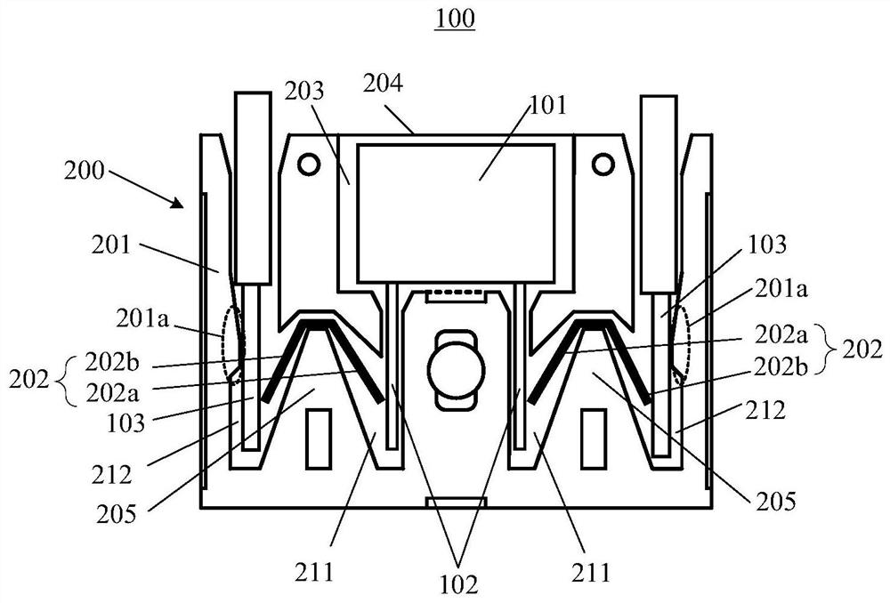
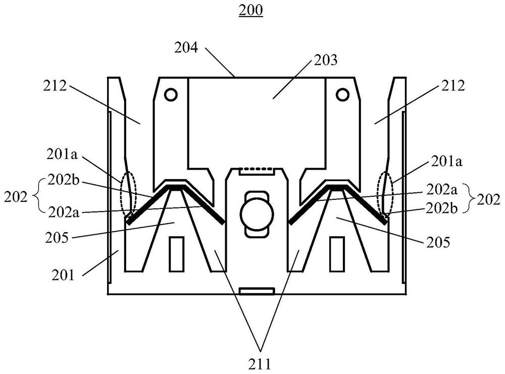
[0038] Embodiments of the present invention provide a housing device of a terminal and a terminal comprising the housing device. refer to figure 1 , figure 1 A schematic cross-sectional structure diagram of a connection terminal 100 according to an embodiment of the present invention.

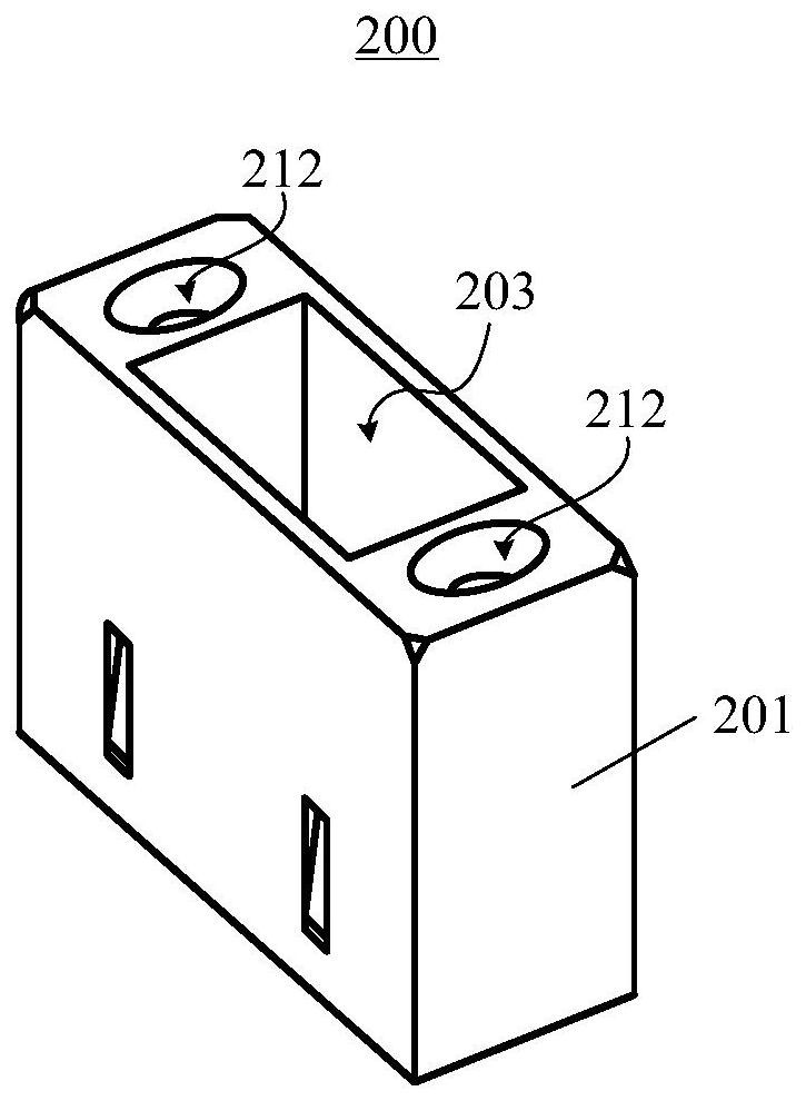
[0039] In some embodiments, the connection terminal 100 may include: a terminal body and a housing device 200, the terminal body may include an impedance element 101, and the two ends of the impedance element 101 are adapted to b...


PUM


Abstract

The invention provides a shell device of a wiring terminal, the wiring terminal and lighting equipment. The wiring terminal comprises a terminal body and the shell device, the terminal body comprisesan impedance element, and the two ends of the impedance element are suitable for being coupled with a driving power source and an illuminating lamp respectively. The shell device includes: a shell having a chamber for accommodating the impedance element; and two conductive joints, wherein each conductive joint is provided with a first end and a second end, the first ends of the two conductive joints are respectively suitable for being detachably and electrically connected with the two ends of the impedance element, and the second ends of the two conductive joints are respectively suitable forbeing coupled with the driving power supply and the illuminating lamp. By means of the shell device of the wiring terminal and the wiring terminal, installation personnel can conveniently adjust impedance parameters of the impedance element in the wiring terminal, on-site setting of illuminance of the illuminating lamp can be completed efficiently and rapidly, and the requirement for product specifications of the illuminating lamp and a driving power source is greatly lowered.

Description

technical field [0001] The invention relates to the technical field of connection terminals, in particular to a casing device of a connection terminal, a connection terminal and lighting equipment. Background technique [0002] Aiming at the various specifications and models of LED drive power in the market, which has brought many inconveniences to production, sales, inventory management, and customer applications, some solutions currently proposed focus on the development of programmable LED drive power. The advantage that the output parameters of the programmable drive power supply can be set twice is used to achieve the purpose of reducing product models and reducing overall inventory. [0003] However, there are also some problems in the practical application of programmable LED driving power: on the one hand, the programming setting circuit of the programmable LED driving power is very complicated, which increases the cost of the single power supply, and is susceptible ...

Claims


Application Information

Patent Timeline
IPC IPC(8): H01R13/66H01R13/02H01R13/46H01R4/48F21V23/06F21Y115/10
CPCH01R13/6616H01R13/02H01R13/46H01R4/48F21V23/06F21Y2115/10
Inventor 陈忠吴彦颉陈恺瑞
Owner SHANGHAI LUMIXESS TECH
Learn More