Single-phase converter DC bus voltage secondary ripple suppression circuit and method
A DC bus voltage, secondary ripple technology, applied in electrical components, output power conversion devices, etc., can solve the problems of large volume, increased system complexity, low power density, etc., to achieve a simple system control method and easy engineering The effect of optimizing the application and suppressing the double frequency fluctuation
- Summary
- Abstract
- Description
- Claims
- Application Information
AI Technical Summary
Problems solved by technology
Method used
Image

Examples
Embodiment Construction
[0029] The present invention will be described in further detail below in conjunction with accompanying drawing and specific embodiment:
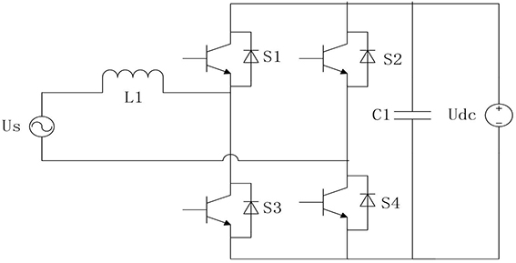
[0030] figure 1 It is a typical H-bridge PWM rectifier circuit in the prior art. When the voltage and current on the AC side of the single-phase converter fluctuate sinusoidally at the same frequency, a secondary pulsating power of the same magnitude as the system power will be generated, which appears as a secondary voltage ripple on the DC side. The expressions of the sinusoidal change of the AC side voltage and current are as follows:
[0031] When the converter operates under the ideal unity power factor, the switch tube frequency is much higher than the grid frequency, ignoring the loss and the switch tube turn-on and turn-off time, assuming the voltage and waveform expressions are as follows:
[0032]
[0033] where U rms , I rms for u s , i s effective value of u s , i s is the instantaneous value of AC voltage and current...
PUM
 Abstract
Description
Claims
Application Information