Cascade H-bridge STATCOM system without electrolytic capacitor and control method

A control method and electrolytic capacitor technology, which is applied in flexible AC power transmission systems, electrical components, circuit devices, etc., can solve problems such as complex control, difficult design of control parameters, overall system cost and volume increase, etc.

Pending Publication Date: 2021-07-06
CHINA UNIV OF MINING & TECH
View PDF0 Cites 0 Cited by
  • Summary
  • Abstract
  • Description
  • Claims
  • Application Information

AI Technical Summary

Problems solved by technology

However, this requires the addition of additional power devices, which will increase the cost and volume of the overall system
Based on the single-phase grid-connected inverter, a small number of scholars have studied the multiplexed active power decoupling technology without adding power switch tubes. The second bridge arm switch tube of the H bridge and the active power decoupling circuit The multiplexing of switching tubes has problems such as complex control and difficult design of control parameters. At the same time, most of the research backgrounds are aimed at a single H-bridge. At present, there is almost no research on the multiplexed active power decoupling control of three-phase cascaded H-bridges. Although the phase-cascaded H-bridge multiplexed active power decoupling control is similar to a single H-bridge, there are many differences. There are still many problems to be solved in the three-phase cascaded H-bridge multiplexed active power decoupling control, so The research of cascaded H-bridge multiplexing active power decoupling control is very necessary

Method used


Image

  • Cascade H-bridge STATCOM system without electrolytic capacitor and control method
  • Cascade H-bridge STATCOM system without electrolytic capacitor and control method
  • Cascade H-bridge STATCOM system without electrolytic capacitor and control method

Examples


Embodiment Construction

[0032] The present invention will be further described below in conjunction with the accompanying drawings and specific embodiments. It should be understood, however, that the invention may be embodied in various forms, and some exemplary and non-limiting embodiments are shown in the drawings and described below, and are not intended to limit the invention to the specific embodiments described. .

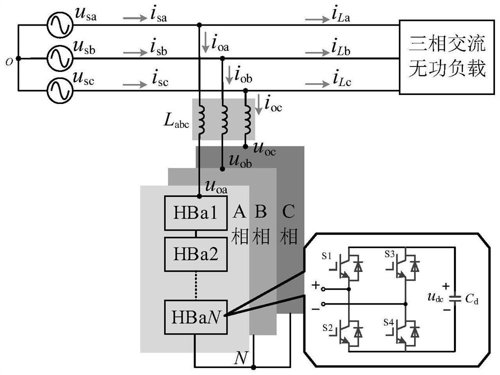
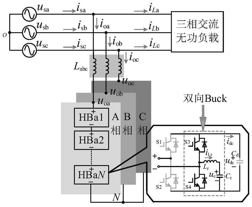
[0033] figure 1 Shown is the main circuit topology of the non-electrolytic capacitor cascaded H-bridge STATCOM system of the present invention, including: three-phase power grid, three-phase reactive load, three-phase filter inductor and three-phase cascaded N Buck multiplexed H-bridges, N ≥2; where the Buck multiplexed H-bridge includes: an H-bridge composed of switch tubes S1~S4, a decoupling inductor L r , two film capacitors C d and C r , C r through L r Connected to the midpoint of the second bridge arm of the H bridge to form a bidirectional Buck circuit, the bidirection...


PUM


Abstract

The invention discloses a cascade H-bridge STATCOM system without an electrolytic capacitor and a control method, and belongs to the field of power electronic control. The system comprises a three-phase power grid, a three-phase reactive load, a filter inductor and N three-phase cascade Buck multiplexing type H bridges, and N is greater than or equal to 2; the Buck multiplexing type H bridge comprises an H bridge formed by switching tubes S1-S4, a decoupling inductor Lr, and two thin-film capacitors Cd and Cr, the Cr is connected to the midpoint of a second bridge arm of the H bridge through the Lr to form a bidirectional Buck circuit, and the bidirectional Buck circuit and the second bridge arm of the H bridge realize switching tube multiplexing; the midpoint of the first bridge arm of the H bridge is connected with the midpoint of the second bridge arm of the previous H bridge, and the three phases are in star connection. On one hand, the bidirectional Buck circuit carries out active power decoupling, H-bridge direct current side fluctuation power is transferred to an auxiliary capacitor Cr through Lr, so that H-bridge direct current side voltage double frequency fluctuation is eliminated, a thin-film capacitor replaces an electrolytic capacitor, meanwhile, an H-bridge first bridge arm is assisted to complete alternating current and direct current side power conversion, and the power density and reliability of the device are improved.

Description

technical field [0001] The invention relates to the field of power electronic control, in particular to a non-electrolytic capacitor cascaded H-bridge STATCOM system and a control method. Background technique [0002] my country is a large country with a vast territory and uneven energy distribution. The abundant electric energy in the northwest needs to be transported to the eastern region through long distances. On the other hand, with the development of science and technology and industry, many high-power reactive loads such as steel rolling mills, mine hoists, and large-capacity transformers have appeared in the power grid. If the reactive power compensation in the power grid is insufficient, this long-distance power transmission will exist. Huge line loss leads to low efficiency of the power grid; in addition, with the depletion of traditional fossil energy, countries around the world are increasingly calling for strengthening the development and utilization of new ener...

Claims


Application Information

Patent Timeline
Patent Type & Authority Applications(China)
IPC IPC(8): H02J3/18H02M7/483
CPCH02J3/1842H02M7/483H02J2203/20Y02E40/10
Inventor 周娟徐高祥钊翔坤李京泽原亚雷王莉赵思涵
Owner CHINA UNIV OF MINING & TECH
Why Eureka
Try Eureka