Friction clutch for motor vehicle powertrain, powertrain unit, transmission unit, and powertrain

A power transmission system, friction clutch technology, applied to the power transmission system. field, to achieve the effect of compact design

Pending Publication Date: 2021-01-12
SCHAEFFLER TECH AG & CO KG
View PDF7 Cites 0 Cited by
  • Summary
  • Abstract
  • Description
  • Claims
  • Application Information

AI Technical Summary

Problems solved by technology

[0003] However, the designs known from the prior art have the disadvantage that...

Method used


Image

  • Friction clutch for motor vehicle powertrain, powertrain unit, transmission unit, and powertrain
  • Friction clutch for motor vehicle powertrain, powertrain unit, transmission unit, and powertrain
  • Friction clutch for motor vehicle powertrain, powertrain unit, transmission unit, and powertrain

Examples


Embodiment Construction

[0036] The drawings are merely schematic in nature and serve only for the understanding of the invention. The same elements have the same reference signs. Different features of various exemplary embodiments can also be freely combined with each other.

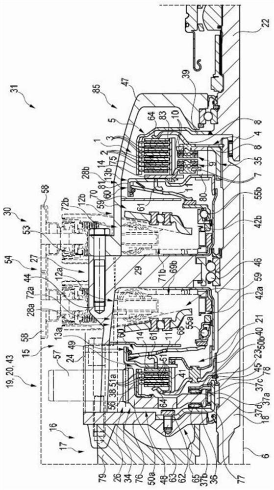
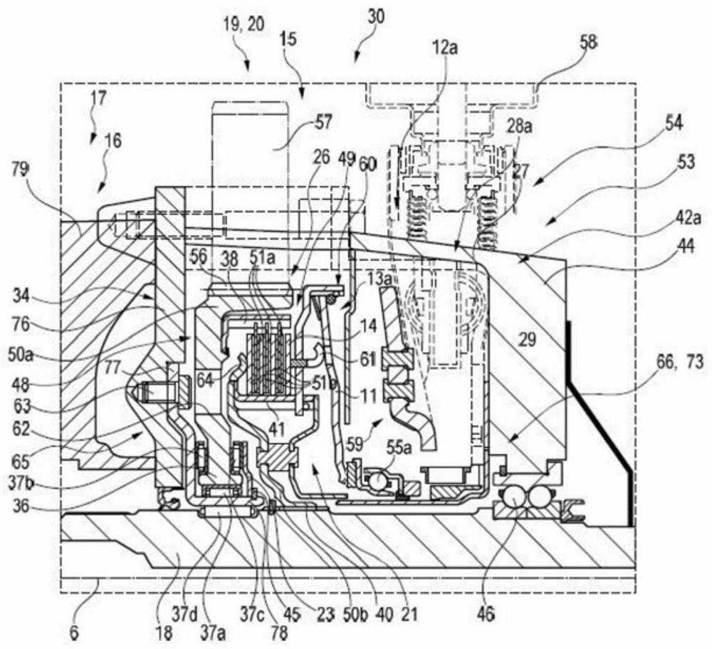
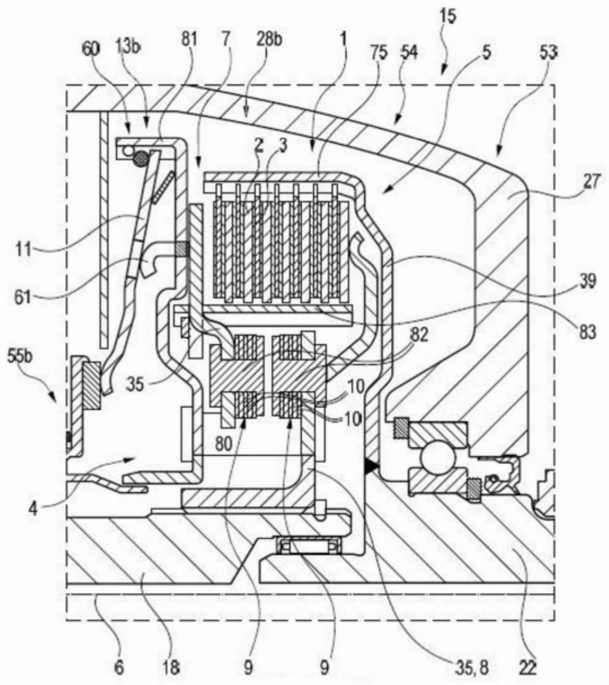
[0037] figure 1 A drive train unit 15 according to the invention is shown constructed according to a first exemplary embodiment. The power train unit 15 has been operatively connected to the transmission 17, which is referred only to its figure 1 shown in the location and in the Figure 6 is further shown in . The drive train unit 15 together with the transmission 17 forms a transmission unit 30 . The transmission 17 is realized as an automatic transmission. An output 16 of the transmission 17 , in the form of a transmission output shaft, is connected in a rotationally fixed manner to an input shaft 18 of the drive train unit 15 . Preferably, the output 16 is connected in a rotationally fixed manner to the input shaft 18...


PUM


Abstract

The invention relates to a friction clutch (1) for a motor vehicle powertrain. The friction clutch comprises two clutch components (4, 5), each of which has at least one friction element (2, 3). The friction elements (2, 3) of the different clutch components (4, 5) lie against each other in a frictionally locking manner in a closed position and are axially spaced from each other in an open position. A first clutch component (4) additionally has a first support part (7), which receives at least one first friction element (2), and a second support part (8), which is rotationally fixed to the first support part (7) by means of at least one leaf spring unit (9). A leaf spring (10) of the at least one leaf spring unit (9) is designed and positioned relative to a reference plane aligned perpendicularly to the rotational axis (6) in a set angle in the closed position such that an additional axial force is applied to the friction elements (2, 3) of the different clutch components (4, 5) in a drive rotational direction of the first clutch component (4). The invention additionally relates to a powertrain unit (15) for the hybrid vehicle, comprising the friction clutch (1), to a transmissionunit (30), and to a powertrain (31).

Description

technical field [0001] The present invention relates to a friction clutch for use in the power train of a motor vehicle, such as an automobile, truck, bus or other commercial vehicle. Furthermore, the invention relates to a drive train unit having said friction clutch, to a transmission unit having a drive train unit, and to a drive train. Background technique [0002] Automatic transmissions for motor vehicles are generally known from the prior art. Clutches are known which can selectively couple the output of the transmission with the wheels of the rear axle in addition to the wheels of the front axle to realize all-wheel drive. [0003] However, the designs known from the prior art have the disadvantage that these clutches have to be designed relatively large in order to transmit high torques. Contents of the invention [0004] It is therefore the object of the present invention to eliminate the disadvantages known from the prior art and in particular to provide a fri...

Claims


Application Information

Patent Timeline
IPC IPC(8): B60K6/387B60K6/48B60K6/52B60K17/344
CPCB60K6/20B60K6/387B60K2006/4808B60K2006/4833B60K6/48B60K6/52F16D13/52F16D21/02F16D2023/126F16D23/14F16D2023/141F16D13/72B60K6/405B60K2006/4825B60Y2200/92B60Y2400/424
Inventor 马克·芬肯策勒奥雷莉·凯勒
Owner SCHAEFFLER TECH AG & CO KG
Why Eureka
Try Eureka