
Tool for brushing in cavity

A brushing and tooling technology, applied in the field of brushing tools in the cavity, to achieve the effect of reducing the bearing weight and increasing the brightness

Pending Publication Date: 2021-01-15
HUNAN LIANCHENG TRACK EQUIP CO LTD
View PDF0 Cites 0 Cited by
  • Summary
  • Abstract
  • Description
  • Claims
  • Application Information

AI Technical Summary

Problems solved by technology

[0004] The purpose of the present invention is to provide a tool for brushing in the cavity to solve the problem of repainting the limited area of ​​the inner wall of the box body parts

Method used


Image

  • Tool for brushing in cavity
  • Tool for brushing in cavity

Examples


Embodiment

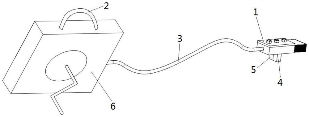
[0028] see Figure 1 to Figure 2 , a tool for brushing in the cavity, this embodiment is applied to the paint brushing on the inner wall of the cavity of the fuel tank.

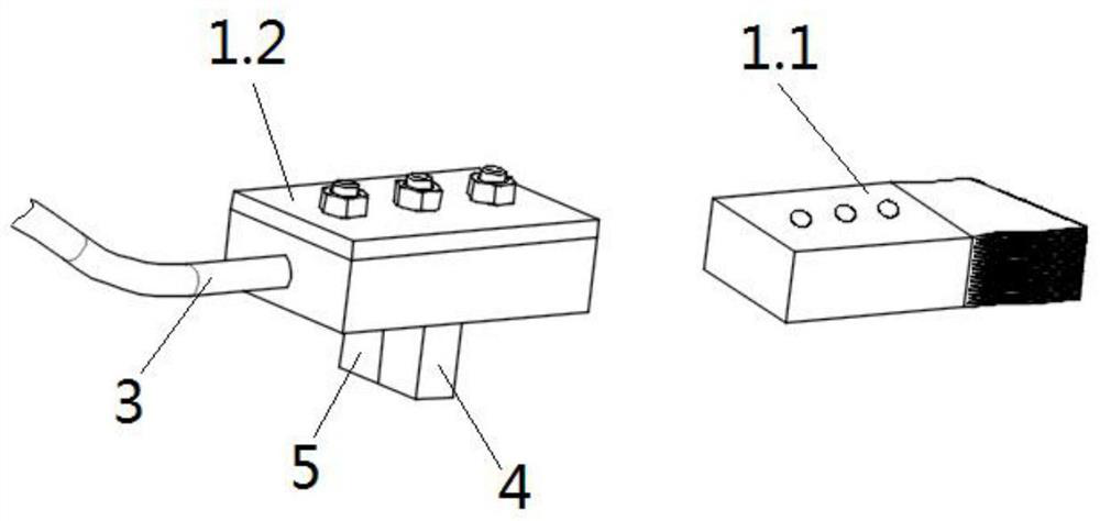
[0029] A tool for brushing in a cavity, including a brush head assembly 1, a handle 2, and an angle adjustment member 3 connected between the brush head assembly 1 and the handle 2, which is convenient for adjusting the position of the brush head assembly 1, and for the oil tank The limited area (dead angle area) of the inner wall of the cavity is repaired; figure 1 As shown, the brush head assembly 1 is provided with a miniature camera 4, which is used to observe the uniformity of the coating inside the fuel tank cavity. Dip the paint on the top, extend the brush head assembly 1 into the inside of the fuel tank cavity, observe the unsprayed area inside the fuel tank body through the micro camera 4, and repaint the area. In this embodiment, the brush head assembly 1 The dimensions of length, width and heigh...


PUM

PropertyMeasurementUnit
diameteraaaaaaaaaa
diameteraaaaaaaaaa

Abstract

The invention provides a tool for brushing in a cavity. The tool comprises a brush head assembly, a handle and an angle adjusting piece connected between the brush head assembly and the handle; a micro camera and a lighting device are arranged on the brush head assembly and are used for observing the uniformity of the coating in the cavity. The brush head assembly and the handle are connected through the angle adjusting piece, the position of the brush head is convenient to adjust, paint supplementary brushing is conducted on the limited area of the inner wall of the box body, the micro camerais arranged on the brush head assembly, the coating uniformity condition in the cavity of the box body is convenient to observe, and supplementary brushing is conducted on the area which is not sprayed; by arranging a lighting device on the brush head assembly, the brightness in the cavity can be increased conveniently, the paint spraying situation in an oil tank cavity can be shot conveniently,and therefore it is confirmed that supplementary brushing is conducted on an uneven spraying area or an unsprayed area.

Description

technical field [0001] The invention relates to the technical field of equipment manufacturing, in particular to a tool for brushing in a cavity. Background technique [0002] At present, when manufacturing tanks such as fuel tanks, pipeline spray guns are used to spray the inside of the tanks. However, due to the presence of structures such as oil passages and oil flow chambers on the tanks, there are ribs and other objects inside the cavity, and the pipeline spray guns The spraying angle cannot be effectively controlled, resulting in that the coating sprayed inside the cavity cannot be sprayed evenly, and there are some areas where spraying is missed. Due to the occlusion, it is often difficult for the human eye to observe the area where the spraying is leaking inside the cavity. However, the brushing tools purchased on the market cannot repaint the restricted area inside the cavity, resulting in often unqualified paint inside the cavity. Pipeline spray guns can only be u...

Claims


Application Information

Patent Timeline
Patent Type & Authority Applications(China)
IPC IPC(8): A46B15/00A46B5/00
CPCA46B5/0079A46B5/0095A46B15/0036A46B15/0044A46B2200/202
Inventor 彪伟蒋虎刘春生郭武冬
Owner HUNAN LIANCHENG TRACK EQUIP CO LTD
Learn More