
Ultraviolet sterilizer for elevator car buttons

A technology of ultraviolet disinfection and elevator car, which is applied in the direction of disinfection, sanitary equipment for toilets, water supply equipment, etc., and can solve the limitations of the scope of use and occasions, the lack of safe disinfection hardware structure, and the structural performance of the safety protection hardware of ultraviolet disinfection equipment Problems such as not being reasonably improved, to achieve the effect of a wide range of use and improved structural performance

Inactive Publication Date: 2021-01-15
许宝民
View PDF0 Cites 1 Cited by
  • Summary
  • Abstract
  • Description
  • Claims
  • Application Information

AI Technical Summary

Problems solved by technology

[0002] At present, in order to further prevent the spread of the virus and effectively cut off the transmission chain of the new coronavirus, ultraviolet disinfection technology has been widely used in daily life, but the existing ultraviolet disinfection equipment placed indoors is in the process of irradiation disinfection. It does not harm humans or other animals, and more is to ensure effective and safe disinfection operations through the implementation of artificial regulations and measures that consume more manpower and labor intensity, in order to prevent the safety of human or other animal physiological organs / tissues and physiological functions The measures cannot be guaranteed or implemented unconditionally, or the existing ultraviolet disinfection equipment lacks the safety hardware structure of its own safety, so the safety protection hardware structure performance of the existing ultraviolet disinfection equipment itself has not been reasonably improved, resulting in its scope of use. The occasion is correspondingly greatly restricted

Method used


Image

  • Ultraviolet sterilizer for elevator car buttons
  • Ultraviolet sterilizer for elevator car buttons
  • Ultraviolet sterilizer for elevator car buttons

Examples


Embodiment Construction

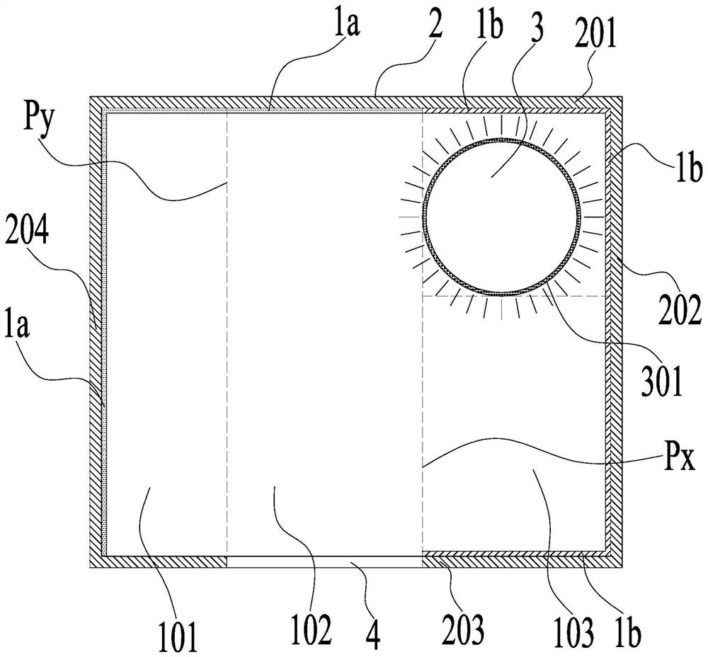
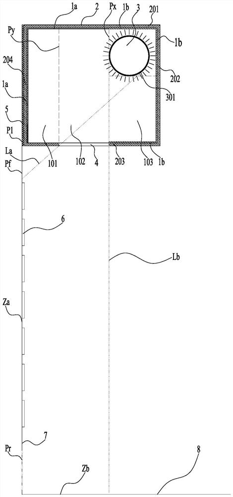
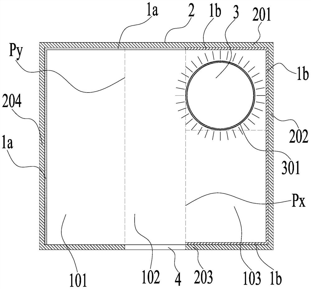
[0025] An elevator car button ultraviolet sterilizer, such as figure 1 -- Figure 16 As shown, the specific structure of the present invention itself is: the cross-sectional structure of the ultraviolet shielding box 2 itself presents a surrounding circumferential box wall, and the surrounding circumferential box wall is divided into a bottom box wall 204, a back box wall 201, a top box wall 202 and a front box wall. The bottom box wall 203, the bottom box wall 204, the back box wall 201, the top box wall 202 and the front box wall 203 are respectively located at the bottom, back, top and front of the ultraviolet shielding box 2, and the front box wall 203 is penetrated with an ultraviolet guide The perforation 4, the first plane Px where the ultraviolet guide hole 4 is closest to the top of the top box wall 202, divides the interior of the ultraviolet shielding box 2 into ultraviolet rays in the direction from the back box wall 201 to the front box wall 203. The source place...


PUM


Abstract

The invention relates to life disinfection and sterilization equipment, in particular to an ultraviolet disinfection appliance for an elevator car button. An ultraviolet guiding hole is formed in thefront box wall in a penetrating manner, a first plane where the topmost part, closest to the top box wall, of the ultraviolet guiding hole is located sequentially divides the interior of an ultraviolet shielding box into an ultraviolet emission source placing bin and an ultraviolet propagation bin in the direction from the back box wall to the front box wall, an ultraviolet irradiation sterilization and disinfection lamp is fixedly arranged in the ultraviolet shielding box and close to the ultraviolet emission source placing bin on the top box wall, and all ultraviolet sources in the ultraviolet irradiation sterilization and disinfection lamp are positioned in the ultraviolet emission source placing bin. The structural performance of a safety protection hardware is greatly improved, the application range and occasions are wide, and the structural performance of the safety protection hardware is more suitable for safe irradiation sterilization operation of keys and buttons in an elevator car.

Description

technical field [0001] The invention relates to domestic disinfection and sterilization equipment, in particular to an ultraviolet disinfection appliance for elevator car buttons. Background technique [0002] At present, in order to further prevent the spread of the virus and effectively cut off the transmission chain of the new coronavirus, ultraviolet disinfection technology has been widely used in daily life, but the existing ultraviolet disinfection equipment placed indoors is in the process of irradiation disinfection. It does not harm humans or other animals, and more is to ensure effective and safe disinfection operations through the implementation of artificial regulations and measures that consume more manpower and labor intensity, in order to prevent the safety of human or other animal physiological organs / tissues and physiological functions The measures cannot be guaranteed or implemented unconditionally, or the existing ultraviolet disinfection equipment lacks t...

Claims


Application Information

Patent Timeline
Patent Type & Authority Applications(China)
IPC IPC(8): A61L2/10A61L2/26
CPCA61L2/10A61L2/26
Inventor 许宝民许闻洋
Owner 许宝民
Learn More