
Mechanical displacement mechanism for welding circular thin-walled workpiece

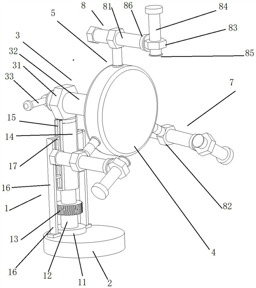
A technology of displacement mechanism and thin-walled parts, applied in welding equipment, auxiliary welding equipment, welding/cutting auxiliary equipment, etc., can solve the problems of insufficient compatibility of equipment, complicated processing of welding displacement machine, etc., and achieve good clamping effect , the effect of reducing wear

Pending Publication Date: 2021-01-15
TIANJIN LOCOMOTIVE CO LTD
View PDF0 Cites 0 Cited by
  • Summary
  • Abstract
  • Description
  • Claims
  • Application Information

AI Technical Summary

Problems solved by technology

[0003] In view of this, the present invention proposes a mechanical displacement mechanism for the welding of circular thin-walled parts to solve the problems of complex processing and insufficient equipment compatibility of traditional welding displacement machines

Method used


Image

  • Mechanical displacement mechanism for welding circular thin-walled workpiece
  • Mechanical displacement mechanism for welding circular thin-walled workpiece
  • Mechanical displacement mechanism for welding circular thin-walled workpiece

Examples


Embodiment Construction

[0031] It should be noted that, in the case of no conflict, the embodiments of the present invention and the features in the embodiments can be combined with each other.

[0032] In describing the present invention, it should be understood that the terms "center", "longitudinal", "transverse", "upper", "lower", "front", "rear", "left", "right", The orientations or positional relationships indicated by "vertical", "horizontal", "top", "bottom", "inner", "outer", etc. are based on the orientation or positional relationships shown in the drawings, and are only for the convenience of describing the present invention Creation and simplification of description, rather than indicating or implying that the device or element referred to must have a specific orientation, be constructed and operate in a specific orientation, and therefore should not be construed as limiting the invention. In addition, the terms "first", "second", etc. are used for descriptive purposes only, and should no...


PUM


Abstract

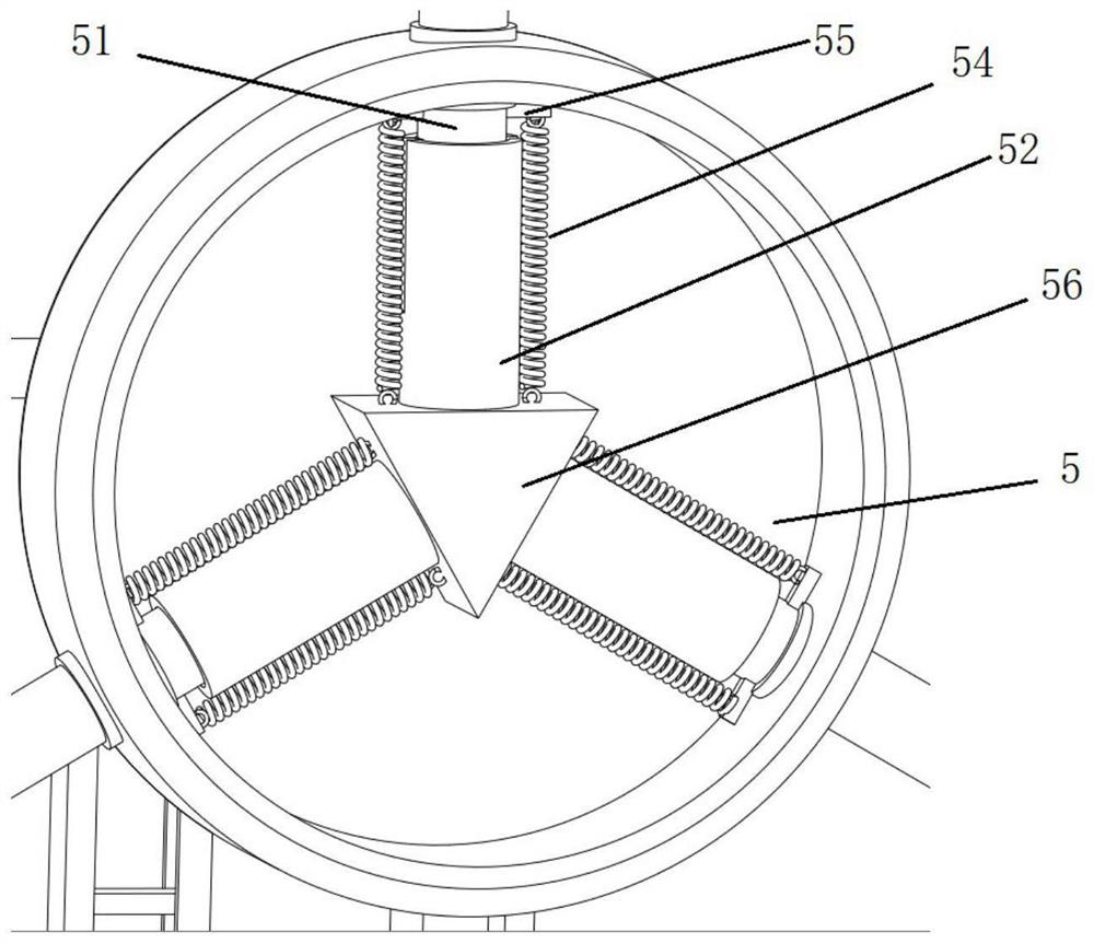
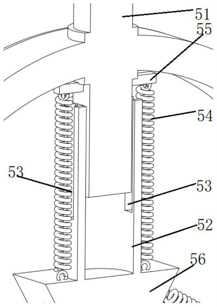
The invention provides a mechanical displacement mechanism for welding a circular thin-walled workpiece. A base, a lifting assembly, a limiting assembly and a clamping assembly are included, the lifting assembly is installed on the base, the limiting assembly is horizontally installed at the top of the lifting assembly through a first nut, the clamping assembly comprises an installation shell, telescopic units and clamping arms, and the installation shell is installed on the limiting assembly. The telescopic units are circumferentially installed in the installation shell through an installation block and each comprises a telescopic rod, a sleeve and an elastic piece, the sleeves are fixed to the installation block, one ends of the telescopic rods are arranged in the sleeves, the other endsof the telescopic rods extend out of the installation shell via through holes reserved in the installation shell, and the ends, away from the installation shell, of the telescopic rods are connectedwith the clamping arms. The ends, away from fixing blocks, of the elastic pieces are connected with the installation block. According to the mechanical displacement mechanism for welding the circularthin-walled workpiece, the problems that a traditional welding displacement machine is complex in machining and insufficient in equipment compatibility are solved.

Description

technical field [0001] The invention belongs to the field of welding auxiliary equipment, and in particular relates to a mechanical displacement mechanism for welding circular thin-walled parts. Background technique [0002] The traditional single-axis welding positioner is mainly composed of a driven unit, an active unit and a base, but the current base is made of an integral welding process, which has many shortcomings, such as inconvenient installation, complicated processing, high cost, and equipment Insufficient compatibility. Contents of the invention [0003] In view of this, the present invention proposes a mechanical displacement mechanism for the welding of circular thin-walled parts to solve the problems of complex processing and insufficient equipment compatibility of traditional welding displacement machines. [0004] In order to achieve the above object, the technical solution created by the present invention is achieved in this way: [0005] A mechanical d...

Claims


Application Information

Patent Timeline
IPC IPC(8): B23K37/047
CPCB23K37/047
Inventor 蔡世刚赵东彬李梦伟白丰林赵淼林田静王欢
Owner TIANJIN LOCOMOTIVE CO LTD
Learn More