Hardware fastening equipment for high-precision hardware machining

A hardware and high-precision technology, which is applied in the field of hardware fastening equipment for high-precision hardware processing, can solve the problems of increased resistance between the clamping block and the slide rail, vibration of hardware processing, and different heights on both sides, so as to maintain the air hole. Smooth, enhance machining accuracy, reduce friction effect

Inactive Publication Date: 2021-01-15
李溪坂
View PDF8 Cites 2 Cited by
  • Summary
  • Abstract
  • Description
  • Claims
  • Application Information

AI Technical Summary

Problems solved by technology

[0003] In order to solve the above-mentioned technology, when using the gantry pliers to clamp the hardware, when the hardware is cut by the cutting machine at high speed, the metal shavings are scattered around the gantry pliers by the force of the cutting knife, and the metal shavings enter the inside of the slide rail, and with the The accumulation of metal shavings increases the resistance between the clamp block and the slide rail, resulting in different heights on both sides of the clamp block, resulting in insufficient clamping force of the hardware, and vibration occurs during hardware processing, which affects the processing accuracy of the hardware. The invention provides a hardware fastening equipment for high-precision hardware processing

Method used


Image

  • Hardware fastening equipment for high-precision hardware machining
  • Hardware fastening equipment for high-precision hardware machining
  • Hardware fastening equipment for high-precision hardware machining

Examples


Embodiment 1

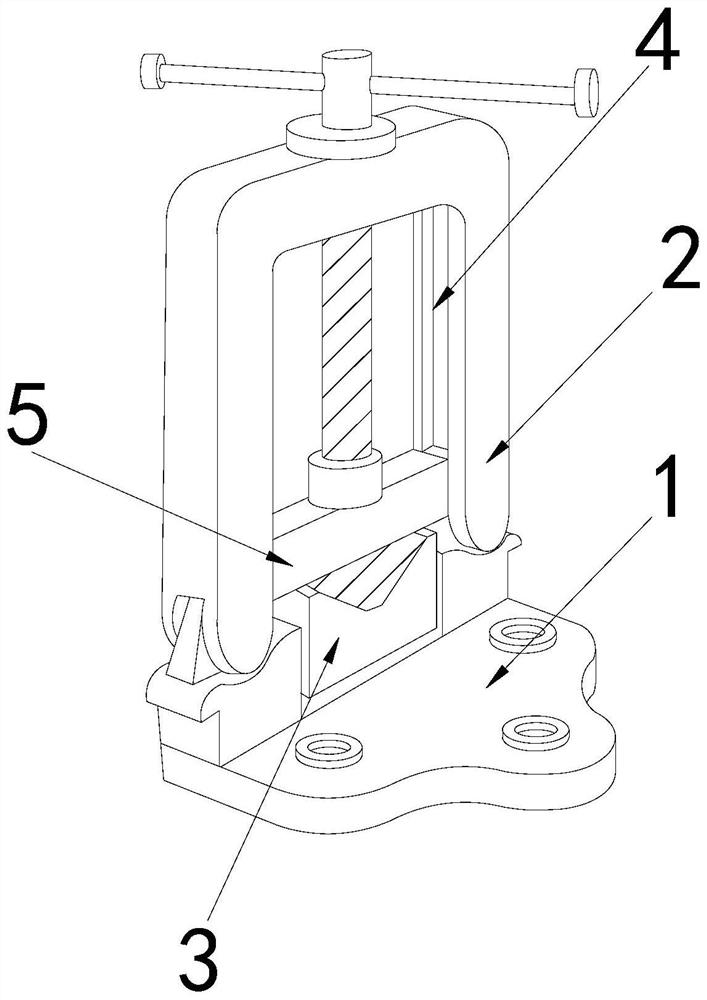
[0027] as attached figure 1 to attach Figure 5 Shown:

[0028] The present invention provides a hardware fastening device for high-precision hardware processing. Its structure includes a base 1, a bracket 2, a supporting platform 3, a slide rail 4, and a clamping block 5. The bracket 2 is vertically welded on the top of the left end of the base 1. The support platform 3 is located on the top of the base 1 and below the inside of the bracket 2 , the slide rail 4 is recessed on the inner wall of the bracket 2 , and the clamping block 5 is movably matched with the slide rail 4 .

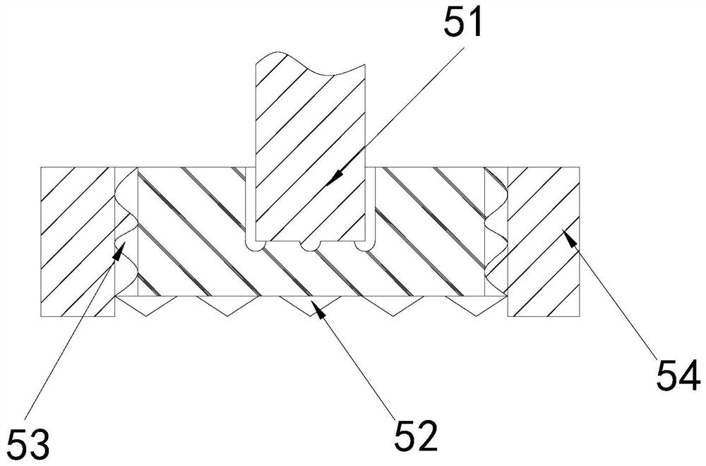
[0029] Described clamp block 5 is provided with screw mandrel 51, teeth 52, connecting block 53, slide block 54, and described screw mandrel 51 is positioned at the middle part of clamp block 5, and described tooth 52 is fixed on clamp block 5 bottom surfaces, and described slide block 54 is installed on both sides of clamping block 5 through connecting block 53.

[0030] Wherein, the slider 54 is p...

Embodiment 2

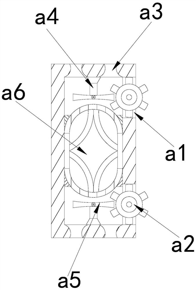
[0036] as attached Image 6 to attach Figure 8 Shown:

[0037]Wherein, the air hole a3 is provided with a bottom groove z1, a pressure plate z2, a reset block z3, and a top block z4, the bottom groove z1 runs through the center of the bottom of the air hole a3, the pressure plate z2 is installed on both sides of the air hole a3, and the reset block z3 is sandwiched between the bottom surface of the pressure plate z2 and the inner wall of the air hole a3, the top block z4 is nested on the top inner wall of the pressure plate z2, and the pressure plate z2 is arc-shaped, which is beneficial to increase the force bearing area with the gas and facilitate the gas to flow along The curved surface of the pressure plate z2 flows.

[0038] Wherein, the top block z4 is provided with a supporting block x1, an air passage x2, and a blocking ring x3, the supporting block x1 is located on both sides of the air passage x2, the blocking ring x3 is installed on the inner wall of the air pass...


PUM


Abstract

The invention discloses hardware fastening equipment for high-precision hardware machining. The hardware fastening equipment structurally comprises a base, a support, a bearing table, a sliding rail and a clamping block, wherein the support is vertically welded to the top of the left end of the base, and the bearing table is located at the top of the base. Due to the fact that metal chips enter the sliding rail, and along with the accumulation of the metal chips, the resistance between the clamping block and the sliding rail is increased; through the cooperation of a sliding block and the sliding rail, gas generated by the deformation of an air bag in the sliding block blows off the metal chips on the inner wall of the sliding rail, so that the accumulation of the metal chips in the sliding rail is reduced, the friction between the clamping block and the sliding rail is reduced, the heights of the two sides of the clamping block are unified, the clamping of a gantry clamp on a hardwareworkpiece is enhanced, and the machining precision of the hardware is enhanced; and due to the fact that the metal chips are subjected to gravity, the metal chips are prone to entering an air hole, the metal chips are blocked through an ejector block in the air hole, the diameter of the air hole is kept unchanged, the air hole is kept open, the emission speed of the gas is increased, the amount of the gas is increased, and the metal chips are blown off more quickly.

Description

technical field [0001] The invention belongs to the field of hardware, and more specifically relates to a hardware fastening device for high-precision hardware processing. Background technique [0002] During the processing of hardware, in order to improve the precision of processing, fastening equipment is used to clamp the hardware to reduce the vibration of hardware processing and affect the precision of hardware. Among them, gantry pliers are the most common type of fastening equipment. The hardware is clamped and processed by the gantry pliers. In order to facilitate the clamping of different sizes of hardware, the gantry pliers are equipped with slide rails to cooperate with the clamping blocks. The height of the clamping blocks can be changed according to the size of the objects to tightly clamp the objects; now In the prior art, when using the gantry pliers to clamp the hardware, when the hardware is cut by the cutting machine at high speed, the metal shavings are sc...

Claims


Application Information

Patent Timeline
Patent Type & Authority Applications(China)
IPC IPC(8): B23Q3/06B23Q11/00
CPCB23Q3/066B23Q11/005
Inventor 李溪坂
Owner 李溪坂
Why Eureka
Try Eureka