A kind of mold core processing device for manufacturing light guide plate

A technology for processing devices and light guide plates, applied to cleaning methods and appliances, chemical instruments and methods, and dust removal, etc., can solve the problems of thick optical films, destroying total reflection of light, and high cost of optical film components, and achieve improvement Long service life, faster and more convenient cutting, and the effect of reducing wear

Active Publication Date: 2021-02-19
YANGXIN TECH SUZHOU
View PDF3 Cites 0 Cited by
  • Summary
  • Abstract
  • Description
  • Claims
  • Application Information

AI Technical Summary

Problems solved by technology

[0002] The known backlight modules can be mainly divided into direct-type and side-type backlight modules. Take the side-type backlight module as an example. The optical structure at the bottom of the light guide plate will destroy the total reflection of light and make the light leave the light guide plate, and then use the optical film set on the top to increase the brightness of the front and control the viewing angle range. In order to make the light energy of the light guide plate can be The effect of being converged to the positive light emission can be achieved by at least using the lower diffuser and matching two BEFs, but the cost of the optical film set used in this method is relatively high, and the thickness of the optical film is relatively thick. Therefore, it is more important to construct the optical structure at the bottom of the light guide plate, so as to improve its light output effect through the microstructure of the light guide plate; in addition, the manufacture of the light guide plate is often formed by using a precision mold core, so the processing of the mold core is more important

Method used


Image

  • A kind of mold core processing device for manufacturing light guide plate
  • A kind of mold core processing device for manufacturing light guide plate
  • A kind of mold core processing device for manufacturing light guide plate

Examples


Embodiment Construction

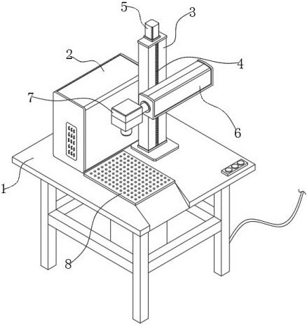
[0028] see Figure 1-7 , in an embodiment of the present invention, a mold core processing device for manufacturing a light guide plate, which includes a processing table 1, a controller 2, a support arm 3, and a telescopic rod 6, wherein the processing table 1 is fixed with a controller 2 and a support arm 3, the support arm 3 is provided with a vertically placed lead screw 4 for rotation, the screw nut seat is connected with a screw nut seat in transmission on the lead screw 4, and the screw nut seat is connected with the telescopic rod 6, and the telescopic The rod 6 is arranged horizontally and attached to the outer surface of the support arm 3, and the screw 4 is also driven and rotated by the adjustment motor 5 fixed on the support arm 3;

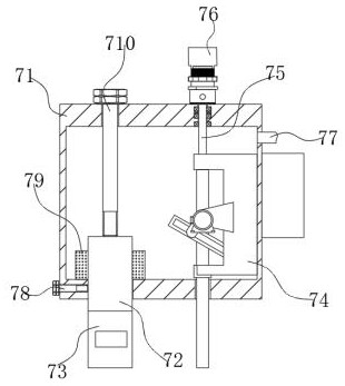
[0029] The telescopic end of the telescopic rod 6 is fixed with a processing head assembly 7, and the processing head assembly 7 can be driven by the telescopic rod 6 to move along the telescopic direction of the telescopic rod 6, so ...


PUM

PropertyMeasurementUnit
angleaaaaaaaaaa
lengthaaaaaaaaaa

Abstract

The invention discloses a mold core processing device for manufacturing a light guide plate, which relates to the technical field of light guide plate mold core manufacturing, and includes a processing table, a controller, a support arm and a telescopic rod, wherein the processing table is fixed with A controller and a support arm, in which a vertically placed lead screw is rotatably arranged, on which the lead screw is driven and connected with a nut seat, the nut seat is connected with a telescopic rod, and the telescopic rod is arranged horizontally and Attached to the outer surface of the support arm, the screw is also driven to rotate by an adjustment motor fixed on the support arm; the telescopic end of the telescopic rod is fixed with a processing head assembly, and the processing head assembly can be controlled by the telescopic rod The drive moves along the expansion and contraction direction of the expansion rod, thereby forming a microstructure on the mold core.

Description

technical field [0001] The invention relates to the technical field of manufacturing a mold core for a light guide plate, in particular to a mold core processing device for manufacturing a light guide plate. Background technique [0002] The known backlight modules can be mainly divided into direct-type and side-type backlight modules. Take the side-type backlight module as an example. The optical structure at the bottom of the light guide plate will destroy the total reflection of light and make the light leave the light guide plate, and then use the optical film set on the top to increase the brightness of the front and control the viewing angle range. In order to make the light energy of the light guide plate can be The effect of being converged to the positive light emission can be achieved by at least using the lower diffuser and matching two BEFs, but the cost of the optical film set used in this method is relatively high, and the thickness of the optical film is relat...

Claims


Application Information

Patent Timeline
Patent Type & Authority Patents(China)
IPC IPC(8): B29C33/38B08B15/04
CPCB08B15/04B29C33/3842
Inventor 周民俊林宏泽李启龙林冠廷房昱赋
Owner YANGXIN TECH SUZHOU
Why Eureka
Try Eureka