Hot melt adhesive rotary labeling machine
A labeling machine and hot-melt adhesive technology, applied in the direction of labeling machine, labeling, labeling, etc., can solve the problems of low production efficiency and low adaptability of bottle models, so as to save equipment costs, avoid surface scratches, simplify The effect of the design structure
- Summary
- Abstract
- Description
- Claims
- Application Information
AI Technical Summary
Problems solved by technology
Method used
Image
Examples
Embodiment 1
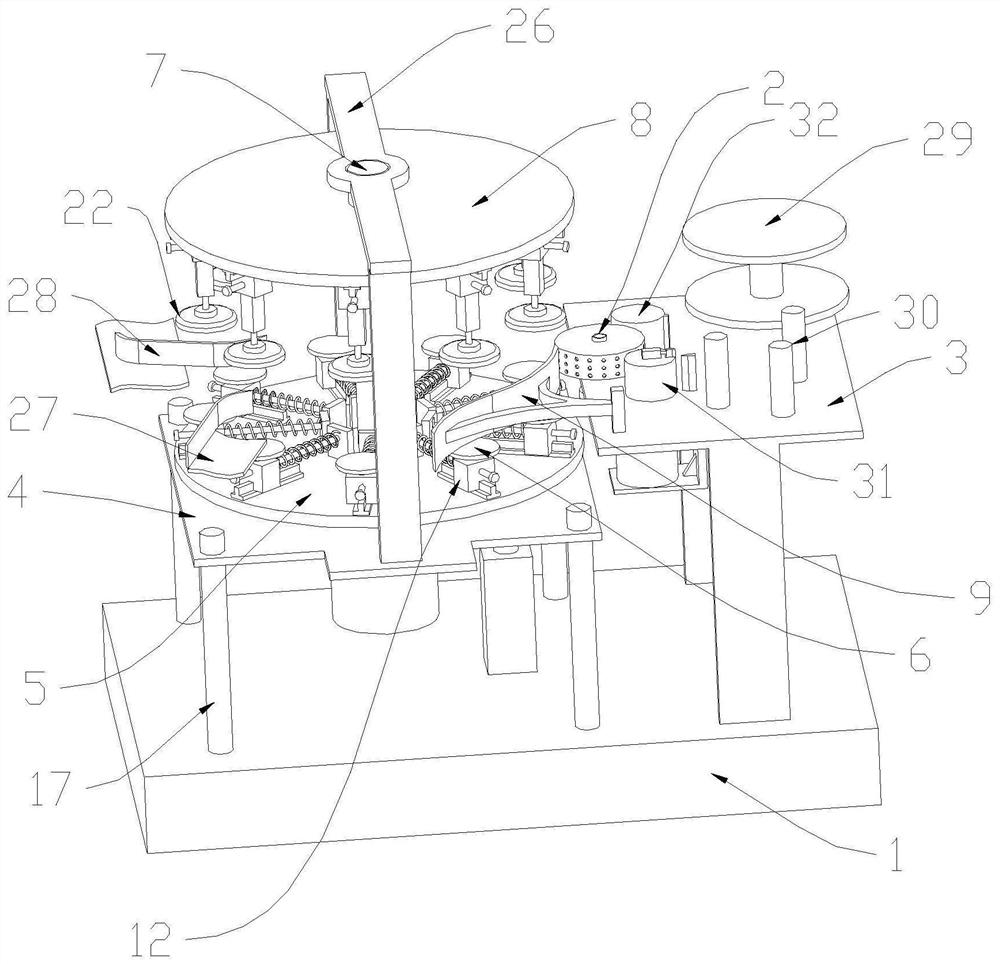
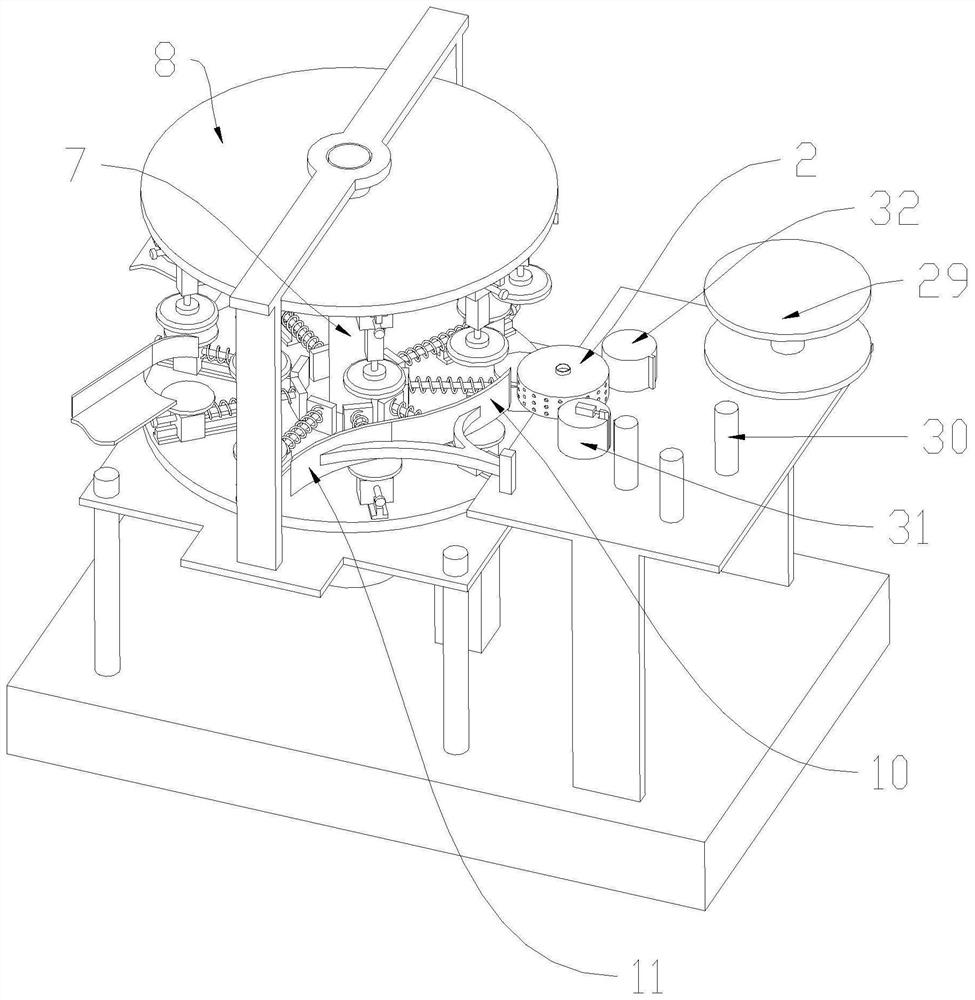
[0035] see Figure 1 to Figure 6 , a hot melt adhesive rotary labeling machine, including a bottle body transmission line, a frame 1, a label plate 29, a label delivery device (not shown), a label delivery roller group 30, a label cutting device 31, a rubber roller mechanism 32 and a gripper Labeling drum 2, wherein, the bottle body transmission line, label feeding device, label feeding roller group, label cutting device, rubber roller mechanism and label grabbing drum 2, etc. are used for conveying, cutting and coating labels. It is a prior art, so it is not too burdensome here. In this embodiment, the label-grabbing drum 2 is a cylindrical structure with an inner cavity, and the inner cavity is connected to an external vacuum generator through the opening at the top of the label-transferring drum. The outer wall of the drum is provided with a plurality of through holes connected to the inner cavity. The through holes are used to absorb the label after the hot melt adhesive i...
Embodiment 2
[0047] After the bottle moves onto the limiting curved plate 9, because the surface of the limiting curved plate 9 is a curved surface structure, when the bottle rolls on the limiting curved plate 9, there is a greater possibility that the bottle will be on the limiting curved plate 9 In the case of sliding, if the bottle slides on the limit bending plate 9, the problem of surface scratches will easily occur. Therefore, in order to reduce the sliding friction of the bottle on the limit bending plate 9, avoid surface scratches on the bottle due to sliding friction problems that affect product quality, see Figure 7 and Figure 8 , design groove 33 on the side wall of limiting bent plate 9, wherein, the long side of groove 33 is arranged along the long side of limiting bent plate 9, is provided with several rotating shafts 34 in the groove 33, and rotating shaft 34 is arranged along the limit The broadside direction of bent plate 9 is arranged, and roller 35 is all rotated on s...
Embodiment 3
[0049] see Figure 9 , in order to improve the adhesive force of the label on the bottle, to improve the product quality, specifically, a pressing bent plate 36 is provided on the other side of the label grabbing drum 2 relative to the limiting bent plate 9, that is, the pressing bent plate 36 Both the limit bending plate 9 are mirror images with respect to the marking drum 2, and the pressing bending plate 36 is concentrically arranged with the central axis 7, and the pressing bending plate 36 is close to the marking drum 2, and the pressing bending plate 36 is rotating The projection on the disk 5 is located within the sliding range of the bottle holder 6 in the radial direction of the rotating disk 5. After the bottle leaves the label grabbing drum 2, driven by the rotating disk 5, the bottle enters the pressing bending plate 36, and the same , driven by the rotating disk 5, and under the limit compression of the pressing curved plate 36 to the bottle, the bottle will roll ...
PUM
 Abstract
Description
Claims
Application Information
 - R&D Engineer
- R&D Manager
- IP Professional
- Industry Leading Data Capabilities
- Powerful AI technology
- Patent DNA Extraction
Browse by: Latest US Patents, China's latest patents, Technical Efficacy Thesaurus, Application Domain, Technology Topic, Popular Technical Reports.
© 2024 PatSnap. All rights reserved.Legal|Privacy policy|Modern Slavery Act Transparency Statement|Sitemap|About US| Contact US: help@patsnap.com


