
Movable molten iron automatic conveying vehicle

A transport vehicle, mobile technology, applied in vehicle components, transportation and packaging, vehicle safety arrangements, etc., can solve problems such as lack of transport and placement structure, frame damage, vehicle body tilt, etc., to avoid damage and improve service life , the effect of improving stability

Inactive Publication Date: 2021-01-15
鄢宏军
View PDF0 Cites 2 Cited by
  • Summary
  • Abstract
  • Description
  • Claims
  • Application Information

AI Technical Summary

Problems solved by technology

[0007] Aiming at the deficiencies of the prior art, the present invention provides a mobile automatic molten iron conveying vehicle, which solves the problem that the existing automatic molten iron conveying vehicle does not have a certain conveying and placing structure when placing the molten iron from the vehicle body to the ground. It makes the molten iron easy to be unstable during the placement process and reduces the convenience of transportation; the current automatic molten iron conveying vehicle is easy to tilt the car body when picking up goods on uneven or sloped ground When the car body does not have a certain balance state, it is prone to rollover, which reduces the safety factor of the car body. When the rear of the forklift is hit, the frame is prone to damage and reduces the service life.

Method used


Image

  • Movable molten iron automatic conveying vehicle
  • Movable molten iron automatic conveying vehicle
  • Movable molten iron automatic conveying vehicle

Examples


Embodiment Construction

[0022] In order to make the purpose, technical solutions and advantages of the embodiments of the present invention clearer, the technical solutions in the embodiments of the present invention will be clearly and completely described below in conjunction with the drawings in the embodiments of the present invention. Obviously, the described embodiments It is a part of embodiments of the present invention, but not all embodiments. Based on the embodiments of the present invention, all other embodiments obtained by persons of ordinary skill in the art without creative efforts fall within the protection scope of the present invention.

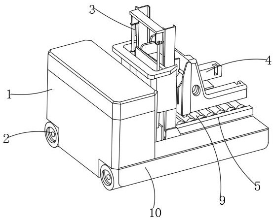
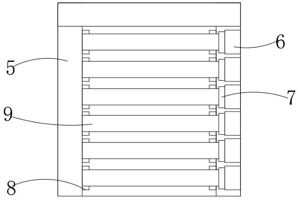
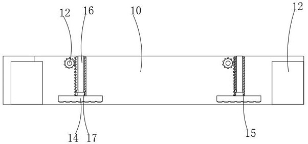
[0023] see Figure 1-4 : A mobile automatic molten iron transport vehicle, comprising a control device 1, a vehicle frame 10 is connected to both sides of the bottom end of the control device 1, and a lifting mechanism 3 is connected between the vehicle frames 10, and a cargo is connected to the rear side of the lifting mechanism 3 The fork 4 is ...


PUM


Abstract

The invention relates to the technical field of molten iron conveying, and discloses a movable molten iron automatic conveying vehicle. The movable molten iron automatic conveying vehicle comprises acontrol device, vehicle frames are connected to the two sides of the bottom end of the control device, a lifting mechanism is connected between the vehicle frames, a pallet fork is connected to the rear side of the lifting mechanism, and a conveying frame is connected between the bottom ends of the vehicle frames. Motors are arranged in one side of the conveying frame, rotating shafts are connected to one sides of the motors, and conveying rollers are connected to one sides of the rotating shafts. Wheels are arranged on the two sides of each frame, a rotating piece is connected to one side ineach frame, a gear is connected to one end of each rotating piece, the gears are in transmission connection with gear cylinders, and fixing plates are connected to the bottoms of the gear cylinders. Connecting rods are connected to the top ends of the interiors of the vehicle frames, the connecting rods are arranged in the gear cylinders, sliding blocks are connected to the bottom ends of the connecting rods, sliding rails are arranged on the two sides of the interiors of the gear cylinders, and the sliding rails are connected with the sliding blocks. According to the movable molten iron automatic conveying vehicle, objects can be conveniently taken down from the device, and meanwhile, the stability of the device is improved.

Description

technical field [0001] The invention relates to the technical field of molten iron transportation, in particular to a mobile automatic molten iron transportation vehicle. Background technique [0002] Conveyor vehicles are widely used in ports, stations, airports, freight yards, factory workshops, warehouses, distribution centers and distribution centers, etc., and can enter cabins, carriages and containers for loading, unloading and handling of palletized goods. Indispensable equipment. In the foundry industry, the molten iron is conveyed to the pouring equipment of the molding line, mainly by means of forklifts conveying through the distance of forks. [0003] There are following deficiencies in the existing automatic molten iron delivery vehicle: [0004] 1. At present, the existing automatic molten iron conveying vehicle does not have a certain conveying and placing structure when placing the molten iron from the car body to the ground, which makes the molten iron prone...

Claims


Application Information

Patent Timeline
IPC IPC(8): B66F9/06B66F9/075B66F9/19B66C23/78B60R19/18F16F15/067
CPCB60R19/18B60R2019/1806B66C23/78B66F9/06B66F9/07504B66F9/07559B66F9/195F16F15/067
Inventor 鄢宏军鄢澄昊
Owner 鄢宏军
Learn More