A road central separation buffer device for road administration engineering
A technology for separating buffers and roads, applied in road safety devices, roads, roads, etc., can solve the problems of driver's body injury, potential safety hazards, and poor urban environment greening effect, so as to reduce frontal collision damage, waste utilization and environmental protection, The effect of using low-cost ingredients
- Summary
- Abstract
- Description
- Claims
- Application Information
AI Technical Summary
Problems solved by technology
Method used
Image
Examples
Embodiment 1
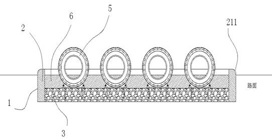
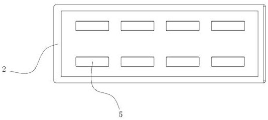
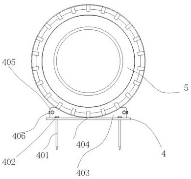
[0035] refer to figure 1 , figure 2 and image 3 As shown, it includes a foundation pit 1 opened between the roads on both sides, and a concrete block 2 is installed along the edge of the interior of the foundation pit 1, and the adjacent concrete blocks 2 are fixed by concrete pouring; The inner bottom of the pit 1 is filled with a stone layer 3, and a plurality of steel plates 4 are arranged symmetrically front and back inside the foundation pit 1, and a through hole is vertically penetrated at the top of the steel plate 4, and a through hole is arranged in the through hole. An anchor rod 401 is inserted into the hole, the upper end of the anchor rod 401 has an end 402, the end end 402 is limited on the top of the steel plate 4, and the anchor rod 401 is inserted downward into the stone layer 3 After inserting, inject concrete slurry in the stone layer 3, pour and fix between the stone layer 3 and the anchor rod 401 after the concrete slurry is injected; a support steel p...
Embodiment 2
[0040] refer to Figure 4 As shown, a vertical shaft 411 is provided at the middle position of the positioning groove 404, and a first through hole is provided at the outer wall of the tire 5, and the diameter of the first through hole is larger than the diameter of the vertical shaft 411. , an elastic pressing block 412 is assembled on the vertical shaft 411, the diameter of the pressing block 412 is larger than the diameter of the first through hole, and a nut 413 is assembled on the vertical shaft 411, and the nut 413 Press against the briquetting block 412 after spinning down; the lower end of the briquetting block 412 is pressed against the inner wall of the tire 5 ; Matching; the outside of the pressure block 412 is provided with a plurality of folding grooves 414; when the tire 5 is impacted, if the tire 5 is rigidly fixed, the elastic deformation of the tire 5 can only be used to absorb energy. After adopting the above structure, the tire 5 can move slightly along the...
Embodiment 3
[0042] refer to Figure 5 and Figure 6 As shown, the end face of the tire 5 is provided with a second through hole 501, and the second through hole 501 is symmetrically arranged in two, and is located on the same diameter line of the tire 5, and the tire 5 The axis of the tire 5 is the center of symmetry; a pipe 502 made of rubber is inserted into the second through hole 501, and an elastic cord 503 is threaded between the two front and rear tires 5, and the elastic cord 503 passes through the The pipeline 502, the end of the elastic rope 503 is connected; the elastic rope 503 is located at a position 16 cm above the soil layer 6; the above-mentioned structure is mainly for offset collision, when the vehicle has an offset collision, the two rows of tires 5, only one row of tires 5 bears the impact, so the energy absorption effect is effective. After adopting the above structure, the wheels on one side of the vehicle need to be elastically blocked by elastic cords to reduce ...
PUM
 Abstract
Description
Claims
Application Information
 - R&D
- Intellectual Property
- Life Sciences
- Materials
- Tech Scout
- Unparalleled Data Quality
- Higher Quality Content
- 60% Fewer Hallucinations
Browse by: Latest US Patents, China's latest patents, Technical Efficacy Thesaurus, Application Domain, Technology Topic, Popular Technical Reports.
© 2025 PatSnap. All rights reserved.Legal|Privacy policy|Modern Slavery Act Transparency Statement|Sitemap|About US| Contact US: help@patsnap.com


