
Temporary combined supporting device for tunnel fracture zone

A supporting device and broken zone technology, which is applied in mine roof supports, mining equipment, earthwork drilling and mining, etc., can solve problems such as rock wall collapse, support damage, and support occupying a large space, and achieve the effect of convenient movement

Inactive Publication Date: 2021-01-15
瞿启芳
View PDF0 Cites 1 Cited by
  • Summary
  • Abstract
  • Description
  • Claims
  • Application Information

AI Technical Summary

Problems solved by technology

[0004] In view of this, the present invention aims to solve the problem that in the initial support device in practical application, since the bracket takes up a relatively large space, it is complicated to transport the bracket in the tunnel, and it is easy to hit the rock wall during the transportation process, causing the rock wall to collapse and the bracket to be damaged. To solve the problem of damage, provide a temporary combined support device for the tunnel fracture zone

Method used


Image

  • Temporary combined supporting device for tunnel fracture zone
  • Temporary combined supporting device for tunnel fracture zone
  • Temporary combined supporting device for tunnel fracture zone

Examples


Embodiment Construction

[0027] The following is further described in detail through specific implementation methods:

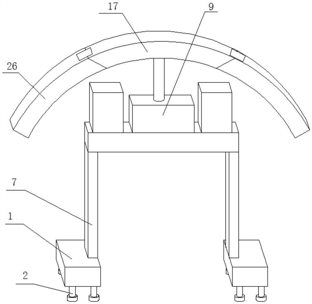
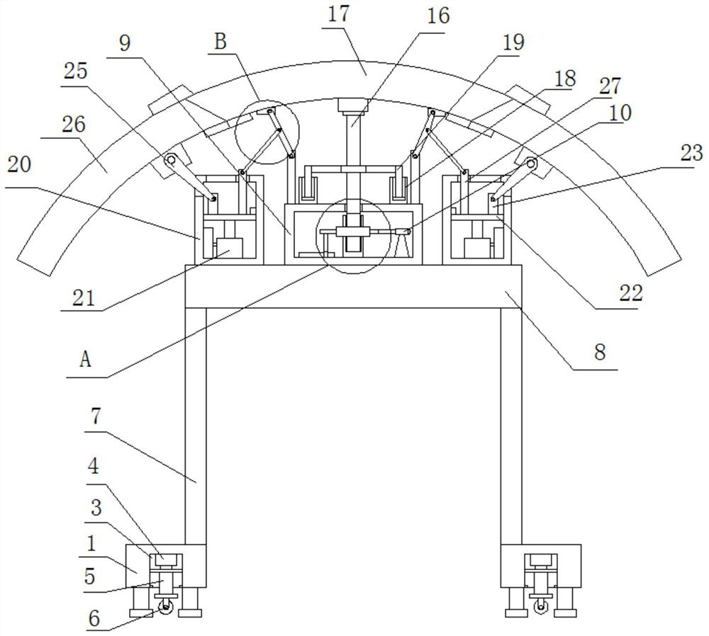
[0028] Such as Figure 1-5A temporary combined support device for the tunnel fracture zone shown, which includes two bases 1, the bottoms of the two bases 1 are fixedly installed with four outriggers 2 arranged in a matrix, and the bottoms of the two bases 1 are provided with Storage tank 3, cylinder 4 is fixedly installed on the top inner wall of the two storage tanks 3, horizontal plates are fixedly installed on the bottom of the output shafts of the two cylinders 4, the two sides of the two horizontal plates are respectively connected with the two sides of the storage tank 3 The inner walls are slidingly connected, and the bottoms of the two horizontal plates are fixedly installed with T-shaped plates 5, and the bottoms of the two T-shaped plates 5 extend to the bottom of the two bases 1 respectively, and the bottoms of the two T-shaped plates 5 are provided with A plurality of u...


PUM


Abstract

The invention belongs to the field of combined supporting equipment, and particularly relates to a temporary combined supporting device for a tunnel fracture zone. A same cross beam is fixedly mountedat the tops of two vertical plates at the top of a base; a supporting seat is fixedly mounted in the center of the top of the cross beam; the top of a vertical shaft of the inner wall of the top of the supporting seat penetrates through the inner wall of the top of the supporting seat and extends to the position above the supporting seat; a main arc-shaped plate is rotationally mounted at the topof the vertical shaft; a supporting component is arranged at the bottom of the vertical shaft; and side face arc-shaped plates are hinged to the two sides of the main arc-shaped plate; the two side face arc-shaped plates are concentric with the main arc-shaped plate; top storage chambers of the cross beam are located on the two sides of the supporting seat correspondingly; a same push plate is mounted on the inner walls of the two sides of each storage chamber in a sliding mode; storage components are rotationally arranged at the tops of the two push plates correspondingly; and the tops of the two storage components are rotationally connected with the bottoms of the two side face arc-shaped plates correspondingly. The problems that a primary supporting device occupies larger space and iscomplex to carry in practical application are solved.

Description

technical field [0001] The invention belongs to the field of combined support equipment and relates to a temporary combined support device for a tunnel broken zone. Background technique [0002] During tunnel construction, it is necessary to determine the length of each longitudinal excavation according to the specific conditions of the rock mass in advance, that is, the entire tunnel is divided into multiple sections of tunnel passages to be excavated sequentially; during construction, the first section of tunnel passage is first excavated according to the excavation length, and then Implement support in this first section of tunnel passage, after completion, continue to excavate the second section of tunnel passage along the longitudinal direction from the end of the first section of tunnel passage, implement support on the second section of tunnel passage, after completion, then At the end of the second section of tunnel passage, a third section of tunnel passage is excav...

Claims


Application Information

Patent Timeline
Patent Type & Authority Applications(China)
IPC IPC(8): E21D23/04
CPCE21D23/0095E21D23/04E21D23/0409
Inventor 瞿启芳
Owner 瞿启芳
Learn More