Steam supplementing valve for turbine

A steam turbine and supplementary steam technology, applied in the field of supplementary gas valve, can solve the problems of unstable vibration, uncontrollable steam flow, large noise, etc., and achieve the effect of satisfying primary frequency modulation

Pending Publication Date: 2021-01-15
HARBIN TURBINE
View PDF0 Cites 0 Cited by
  • Summary
  • Abstract
  • Description
  • Claims
  • Application Information

AI Technical Summary

Problems solved by technology

[0003] The purpose of the present invention is to provide a steam supply valve for steam turbines in order to overcome the problems of unstable vibration, inability to control steam flow and large noise generated by the existing air supply valve at a small opening

Method used


Image

  • Steam supplementing valve for turbine
  • Steam supplementing valve for turbine

Examples


specific Embodiment approach 1

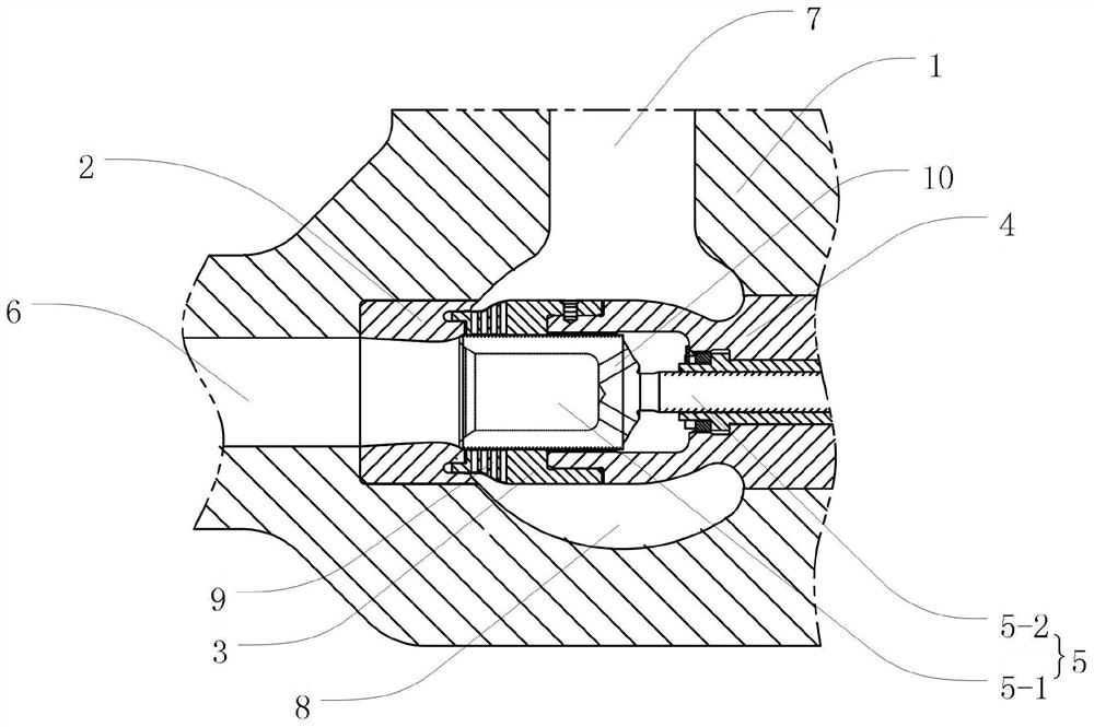
[0018] Embodiment 1. A steam supplement valve for a steam turbine in this embodiment includes a valve housing 1, a valve seat 2 located in the valve housing 1, a hole valve butterfly 3, a valve cover 4 and a steam supplement regulating valve butterfly 5;

[0019] The valve casing 1 is provided with an air inlet passage 6, an air outlet passage 7 and a valve cavity 8, and one end of the air inlet passage 6 and one end of the air outlet passage 7 communicate with the outside respectively; One end communicates with the valve cavity 8 respectively;

[0020] The valve seat 2, the orifice valve butterfly 3 and the bonnet 4 are all tubular, and one end of the valve seat 2, one end of the orifice valve butterfly 3 and the bonnet 4 are connected coaxially in sequence;

[0021] The outer wall of the valve seat 2 is fixed and sealed with the inner wall of the valve housing 1, and the other end of the valve seat 2 communicates with the other end of the intake passage 6;
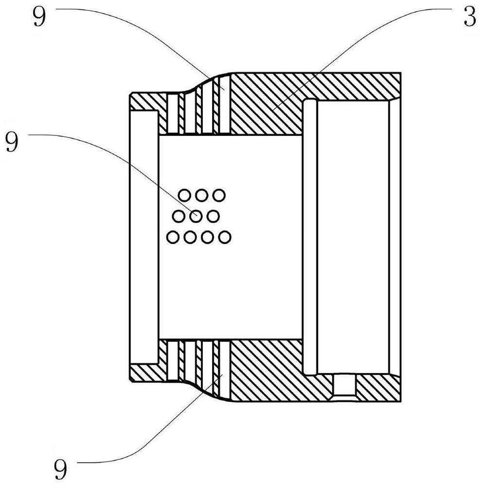
[0022] The side...


PUM


Abstract

The invention relates to a gulp valve, in particular to a steam supplementing valve for a turbine, and aims at solving the problems that an existing gulp valve generates unstable vibration under the small opening degree, cannot control steam flow and generates very large noise. The steam supplementing valve comprises a valve shell, a valve seat, a hole type valve butterfly, a valve deck and a steam supplementing adjusting valve butterfly, wherein the valve seat, the hole type valve butterfly, the valve deck and the steam supplementing adjusting valve butterfly are located in the valve shell. The valve seat, the hole type valve butterfly and the valve deck are all tubular, and one end of the valve seat, one end of the hole type valve butterfly and one end of the valve deck are sequentiallyand coaxially communicated. A plurality of flow control holes are formed in the side wall of the hole type valve butterfly and are all communicated with a valve cavity; the steam supplementing adjusting valve butterfly can move in the axial direction of the hole type valve butterfly and the valve deck when rotating; when the steam supplementing adjusting valve butterfly is located at the side deadpoint of the valve seat, the other end of the valve seat and all the flow control holes are sealed through the steam supplementing adjusting valve butterfly; when the steam supplementing adjusting valve butterfly moves towards the side of the valve deck, the steam supplementing adjusting valve butterfly is gradually exposed out of the flow control holes; and when the steam supplementing adjustingvalve butterfly is located at the side dead point of the valve deck, all the flow control holes are exposed.

Description

technical field [0001] The invention relates to an air supplement valve, in particular to a steam supplement valve with a hole-type valve butterfly which has the function of silencing sound and can precisely control the flow of steam. Background technique [0002] The existing steam intake valve in use adopts a plunger structure design. Since the flow area of ​​the supplementary steam valve must have the ability to flow through the maximum flow of supplementary steam, the flow area of ​​the valve should be designed to be large enough. However, the steam turbine only needs a small supplementary steam flow during a frequency adjustment, and the supplementary gas valve often works at a small opening. Due to the large difference in steam pressure between the front and back of the steam supply valve, the steam flow rate at the joint between the steam supply valve butterfly and the valve seat is very high, so the supply valve produces unstable vibration at a small opening, and it...

Claims


Application Information

Patent Timeline
IPC IPC(8): F01D17/10F01D17/14F01D25/04
CPCF01D17/10F01D17/148F01D25/04
Inventor 王洪鹏袁晶晶潘文娟李涛于丽肖辉敏周新灵赵洪羽郝丹李雅武
Owner HARBIN TURBINE
Why Eureka
Try Eureka