Bionic condensation enhanced heat transfer surface

An enhanced heat transfer, bionic technology, applied in heat transfer modification, steam/steam condenser, heat exchange equipment, etc., can solve the problem of efficient fusion and self-renewal of unfavorable droplets, increased difficulty of droplet nucleation, and update rate Slow and other problems, to achieve the effect of accelerating discharge, increasing nucleation density, and improving efficiency

Inactive Publication Date: 2021-01-15
SOUTHEAST UNIV
View PDF5 Cites 3 Cited by
  • Summary
  • Abstract
  • Description
  • Claims
  • Application Information

AI Technical Summary

Problems solved by technology

However, the reduction of the surface energy of the chemically modified condensing surface will increase the difficulty of nucleation of droplets; the random distribution of condensed droplets on a homogeneous hydrophobic surface is not conducive to the efficient fusion and self-renewal of these droplets; condensed droplets also rely on Gravity-driven ejection, which has a slower update rate and still has a higher thermal resistance

Method used


Image

  • Bionic condensation enhanced heat transfer surface
  • Bionic condensation enhanced heat transfer surface
  • Bionic condensation enhanced heat transfer surface

Examples


Embodiment 1

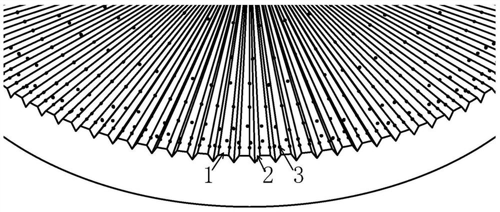
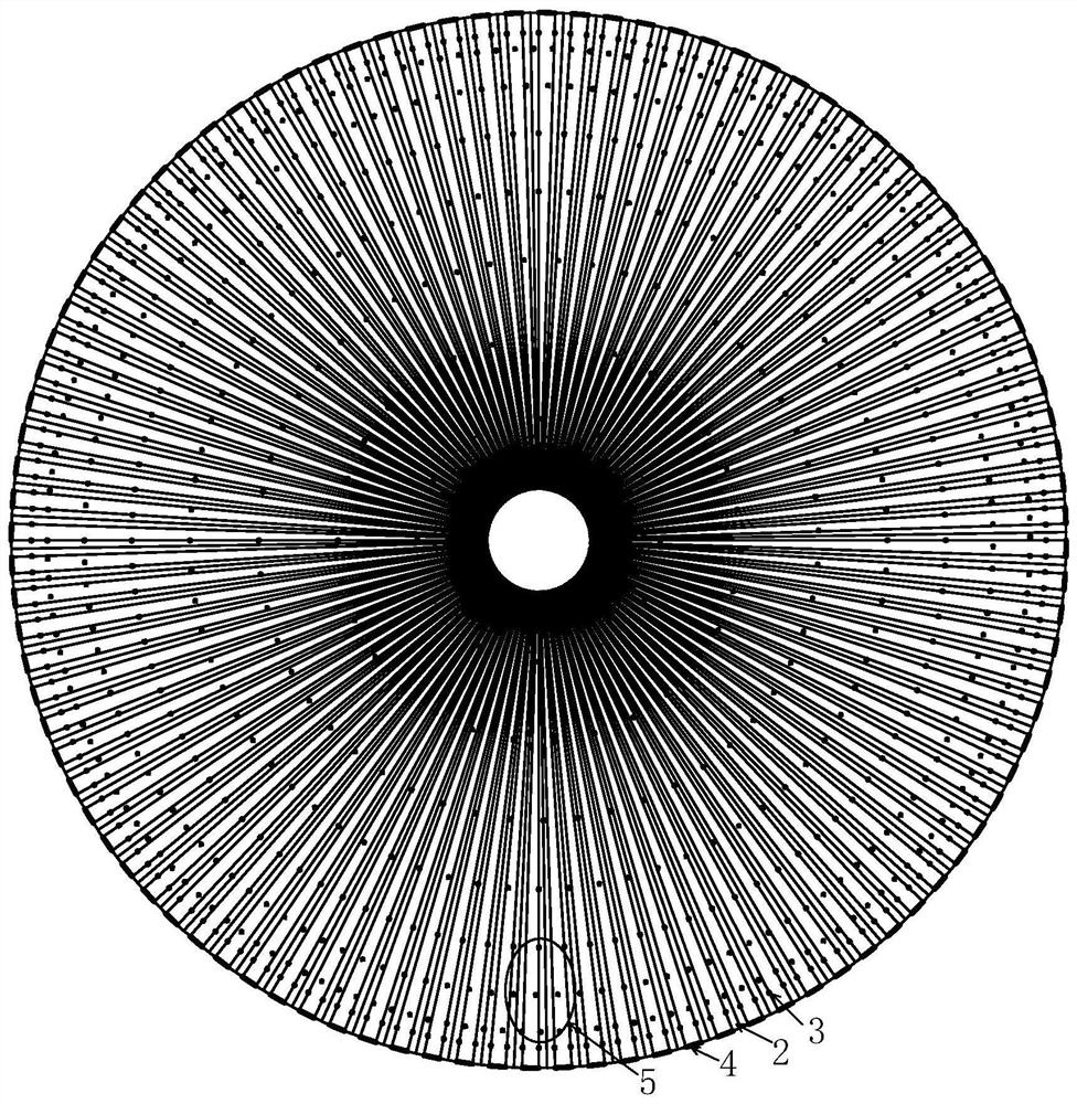
[0027] Such as figure 2 Shown is a plan view of a horizontally placed circular condensation surface 4 and a condensation drop 5 on the circular condensation surface. The cross-sectional area of ​​the hydrophobic micro-grooves distributed on the circular condensation surface 4 increases gradually along the radial direction, and the distribution density of the hydrophilic nucleation points on the circular condensation surface 4 is as follows: figure 2 The direction shown becomes larger along the direction where the width of the hydrophobic microchannel becomes larger. Such as figure 2 As shown, if the area covered by the condensate droplets 5 is divided into two along the vertical direction, the number of hydrophilic nucleation points in the covered area on one side near the center of the circle is smaller than that in the area on the other side. The number of nucleation points. Since the surface free energy of the circular condensing surface 4 becomes larger along the dir...

Embodiment 2

[0054] Such as Figure 4 Shown is a rectangular condensation surface 6 .

[0055] The distribution mode of the hydrophobic microchannel 2 structures distributed on the rectangular condensation surface 6 is as follows Figure 4 As shown, the cross-sectional area gradient changes along the length direction of the hydrophobic microchannel, and the interval between every two adjacent hydrophobic microchannels is consistent with the width of two adjacent hydrophobic microchannels.

[0056] The distribution mode of the structure of the hydrophilic nucleation points 3 distributed on the rectangular condensation surface 6 is as follows Figure 4 As shown, the surface of the hydrophilic nucleation point 3 is a hydrophilic surface with a circular shape. A plurality of hydrophilic nucleation points distributed in the hydrophobic microchannel 2 positions of the same width constitute an artificial hydrophilic nucleation column, and the hydrophilic nucleation points 3 in the same artifici...


PUM


Abstract

The invention discloses a bionic condensation enhanced heat transfer surface. The bionic condensation enhanced heat transfer surface comprises a substrate, micro-channels and hydrophilic nucleation points, wherein the substrate has hydrophobicity; the micro-channels are dispersed on the substrate at the same central angle in the radial direction of a circle center, and the circle center is locatedon the substrate or not located on the substrate; the hydrophilic nucleation points are distributed on the substrate; and the width between the adjacent micro-channels is increased in a gradient manner in the length direction. According to the condensation heat transfer surface, the surface free energy gradient is used for generating driving force on condensed liquid drops, liquid discharging ofa condensation surface is accelerated, nucleation of the condensed liquid drops on the condensation surface is accelerated through the hydrophilic nucleation points distributed on the surface of a hydrophobic substrate, a more stable bead-shaped condensation process is formed on the condensation surface, and smooth conduction of condensation circulation is guaranteed. The bionic condensation enhanced heat transfer surface can effectively improve the nucleation and updating rate of the condensed liquid drops, ensure continuous and stable bead-shaped condensation behaviors and enhance the condensation phase change heat transfer performance.

Description

technical field [0001] The invention relates to a condensation-enhanced heat transfer surface, in particular to an artificial nucleation site and a surface designed to increase the nucleation and renewal rate of condensed droplets, maintain surface bead-like condensation, and realize high-efficiency heat exchange. The condensing surface characterized by gradient grooves can effectively enhance condensing heat transfer. Background technique [0002] With the rapid development of technologies such as electronic information technology and micro-electro-mechanical systems (MEMS), electronic equipment is developing towards miniaturization, integration, and high power. Due to the reduction in physical size and the increase in device capacity, the challenge of efficient heat dissipation with high heat flux in a small-scale space is becoming increasingly severe. Designing and developing high-efficiency condensing heat transfer surfaces will help solve the heat dissipation technolog...

Claims


Application Information

Patent Timeline
Patent Type & Authority Applications(China)
IPC IPC(8): F28B9/00F28B9/08F28F1/36F28F13/00
CPCF28F1/36F28B9/00F28B9/08F28F13/00
Inventor 吴苏晨孙帅杰张程宾邓梓龙
Owner SOUTHEAST UNIV
Why Eureka
Try Eureka