
Traffic signal lamp recognition device for unmanned driving

A traffic signal light and identification device technology, applied in the field of unmanned traffic signal identification devices, can solve problems such as data inaccuracy, and achieve the effects of increasing driving safety, achieving stability, and improving convenience.

Pending Publication Date: 2021-01-15
NANJING UNIV OF AERONAUTICS & ASTRONAUTICS
View PDF0 Cites 0 Cited by
  • Summary
  • Abstract
  • Description
  • Claims
  • Application Information

AI Technical Summary

Problems solved by technology

However, the difficulty of unmanned driving technology lies in the ability to distinguish traffic lights and the surrounding environment, which may lead to inaccurate data collected by the unmanned driving system.

Method used


Image

  • Traffic signal lamp recognition device for unmanned driving
  • Traffic signal lamp recognition device for unmanned driving
  • Traffic signal lamp recognition device for unmanned driving

Examples


Embodiment Construction

[0022] The present invention will be further described below in conjunction with the accompanying drawings.

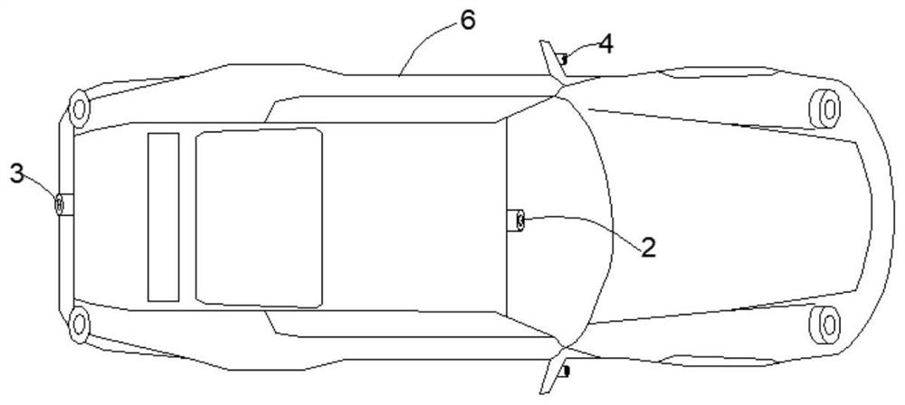
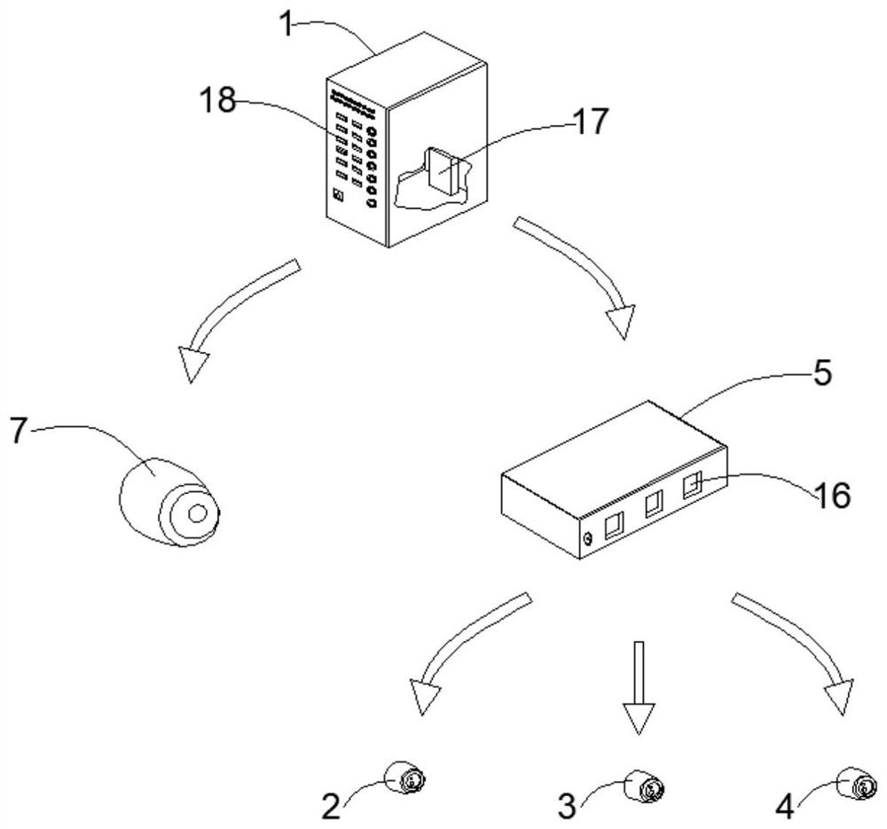
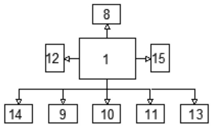
[0023] Such as Figure 1-4 The shown traffic signal recognition device for unmanned driving includes an unmanned vehicle 6 , an MCU master controller 1 , a first camera 2 , and a decoder 5 . Wherein the first camera 2 is located at the top of the front windshield of the unmanned vehicle 6 . The decoder 5 is also provided with a converter 16 . The first camera 2 is provided with a cooperating photoreceptor, and the captured image information and the optical signal of the photoreceptor are transmitted to the decoder 5 through the converter 16 . The MCU general controller 1, the decoder 5 and the driving computer of the unmanned vehicle 6 are integrated.

[0024] The MCU general controller 1 includes an initialization module 19 , a detection and selection module 20 , an operation module 21 and a data storage module 22 . The operation module 21 also includes a detectio...


PUM


Abstract

The invention discloses a traffic signal lamp recognition device for unmanned driving. The traffic signal lamp recognition device comprises an unmanned vehicle, an MCU master controller, a first camera and a decoder, wherein the first camera is located at a top end of a front windshield of the unmanned vehicle; the decoder further comprises a converter; the first camera is provided with a photoreceptor which is installed in a matched mode, and the shot image information and an optical signal of the photoreceptor are transmitted to a decoder through a converter; the MCU master controller, the decoder and a trip computer of the unmanned vehicle are integrally arranged; the MCU master controller comprises an initialization module, a detection selection module, an operation module and a data storage module; the operation module further comprises a detection operation module, a data interaction module and a recombination deployment module; the decoder comprises a signal lamp identificationmodule and a signal time identification module.

Description

technical field [0001] The invention relates to the technical field of unmanned driving, and mainly relates to a traffic signal light recognition device for unmanned driving. Background technique [0002] The current self-driving technology basically has the ability to operate and drive automatically. For example, advanced instruments such as cameras, radar sensors, and laser detectors are installed on the car, and they are used to perceive the speed limit signs and roadside traffic signs on the road, as well as the surrounding environment. The movement of vehicles, people only need to use the map to navigate when they travel. The unmanned driving system mainly uses on-board sensors to perceive the surrounding environment of the vehicle, and controls the steering and speed of the vehicle according to the road, vehicle position and obstacle information obtained by perception, so that the vehicle can drive safely and reliably on the road. [0003] At present, unmanned vehicle...

Claims


Application Information

Patent Timeline
Patent Type & Authority Applications(China)
IPC IPC(8): G08G1/01G08G1/04G08G1/0967G08G1/16B60W10/18B60W10/20B60W40/00G06K9/00G06K9/40
CPCG08G1/0104G08G1/04G08G1/096725G08G1/161B60W10/18B60W10/20B60W40/00B60W2555/60B60W2050/0043B60W2710/18B60W2710/20G06V20/584G06V10/30
Inventor 孙梦蝶吴一全朱梦雅
Owner NANJING UNIV OF AERONAUTICS & ASTRONAUTICS
Learn More