Oil cooling structure of traction motor
A traction motor and cooling structure technology, applied in the direction of motors, electric vehicles, electric components, etc., can solve the problems of affecting the service life of bearings, temperature sensitivity, and the failure of the motor to operate normally, and achieve the effect of improving efficiency and working performance.
- Summary
- Abstract
- Description
- Claims
- Application Information
AI Technical Summary
Problems solved by technology
Method used
Image
Examples
Embodiment 1
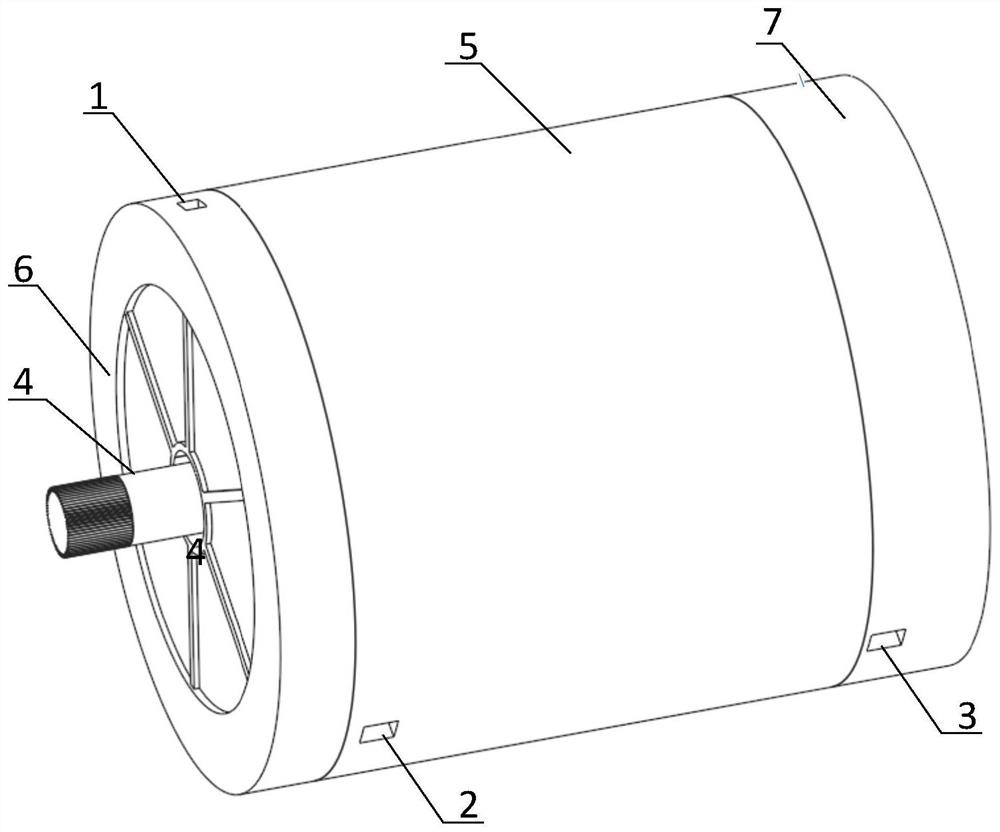
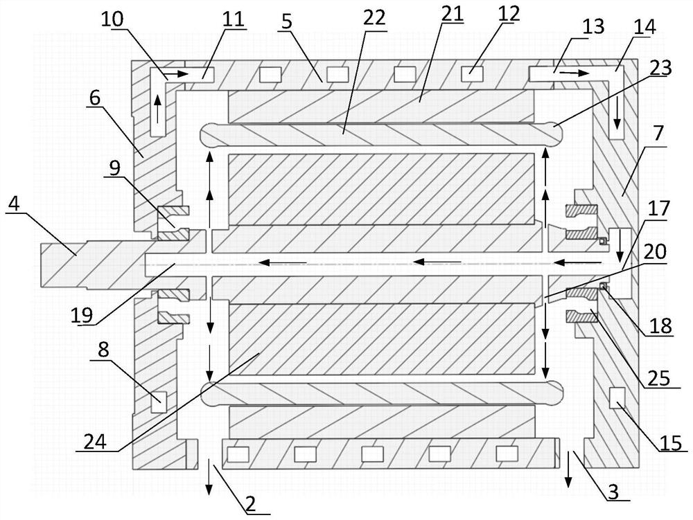
[0030] combine Figure 1-Figure 6, an oil cooling structure of a traction motor provided in an embodiment of the present invention, the traction motor includes: a stator core 21, a coil winding 22, a stator end winding 23, a rotor core 24, a non-drive end bearing 25, a drive end bearing 9. Rotor hollow shaft 4, casing 5, drive end cover 6 and non-drive end cover 7, the casing 5, drive end cover 6 and non-drive end cover 7 constitute a closed structure, and casing 5 is provided with The first cooling pipeline 12, the oil cooling cooling structure includes: an oil inlet 1 opened on the upper end of the driving end cover, an oil outlet 2 opened on the lower end of the casing, and an oil outlet 2 opened on the lower end of the non-driving end cover The oil outlet 3, the second cooling pipeline 8 opened on the driving end cover 6, the third cooling pipeline 15 opened on the non-driving end cover 7, the axial center of the non-driving end cover 7 Temporary storage oil tank 17, a co...
Embodiment 2
[0035] As an optional embodiment of the present invention, in combination with figure 1 , figure 2 , figure 2 as well as Figure 4 , the oil outlet 10 of the second cooling pipeline 8 communicates with the inlet 11 of the first cooling pipeline 12, the oil outlet 13 of the first cooling pipeline 12 communicates with the inlet 14 of the third cooling pipeline 15, and the outlet of the third cooling pipeline 15 The oil port 16 communicates with a temporary storage oil tank 17 , and the temporary storage oil tank 17 communicates with a cooling pipeline 19 .
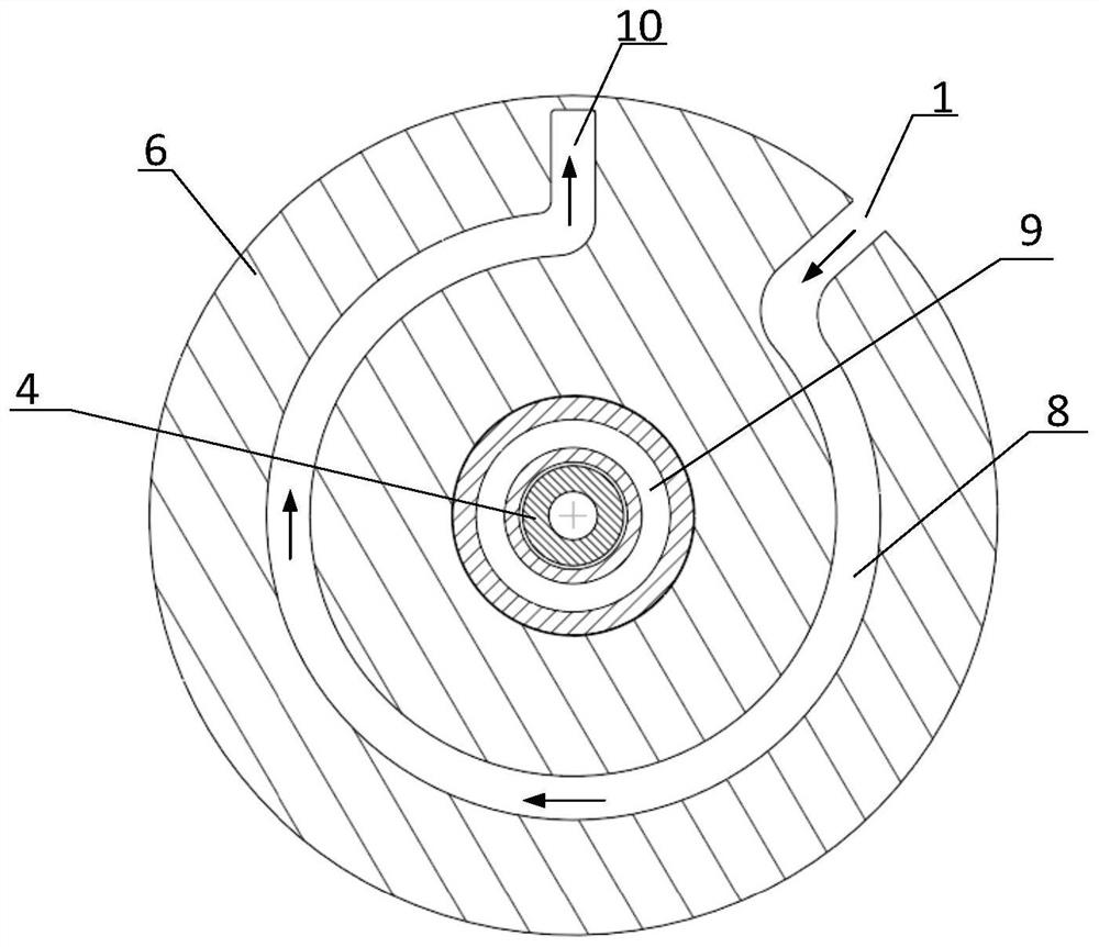
[0036] Such as image 3 As shown, the cooling oil enters the cooling passage 8 through the oil inlet 1 opened on the end cover 6 of the driving end, and circulates in the cooling passage 8 .
[0037] Such as Figure 4 as shown, Figure 4 It is a perspective view of the cooling pipeline in the casing of the oil-cooled traction motor in the embodiment. The cooling oil enters the cooling passage inlet 11 in the casing 5...
Embodiment 3
[0039] As an optional embodiment of the present invention, refer to figure 2 , the storage tank 17 is provided with a rotary seal 18 for preventing the cooling oil in the storage tank 17 from leaking.
[0040] Such as Figure 5 As shown, the cooling oil flows out through the oil outlet 13 of the casing and enters the pipeline inlet 14 of the non-driving end cover, then enters the non-driving end cover pipeline 15 to circulate, and finally flows out through the oil outlet 16 of the non-driving end cover pipeline And enter the temporary storage oil tank 17, then the cooling oil enters the inner pipeline 19 of the rotor hollow shaft 4 through the storage oil tank 17.
PUM
 Abstract
Description
Claims
Application Information
 - R&D
- Intellectual Property
- Life Sciences
- Materials
- Tech Scout
- Unparalleled Data Quality
- Higher Quality Content
- 60% Fewer Hallucinations
Browse by: Latest US Patents, China's latest patents, Technical Efficacy Thesaurus, Application Domain, Technology Topic, Popular Technical Reports.
© 2025 PatSnap. All rights reserved.Legal|Privacy policy|Modern Slavery Act Transparency Statement|Sitemap|About US| Contact US: help@patsnap.com


