Pulse per second generating device and method and measuring system and method of digital clock
A technology of generating device and pulse generating circuit, which is applied in the field of digital clock measurement, can solve the problems of inability to quantitatively measure digital clocks, have no second pulse output function, and low time display resolution, and achieve accurate measurement and calibration. Effect
- Summary
- Abstract
- Description
- Claims
- Application Information
AI Technical Summary
Problems solved by technology
Method used
Image
Examples
Embodiment 1
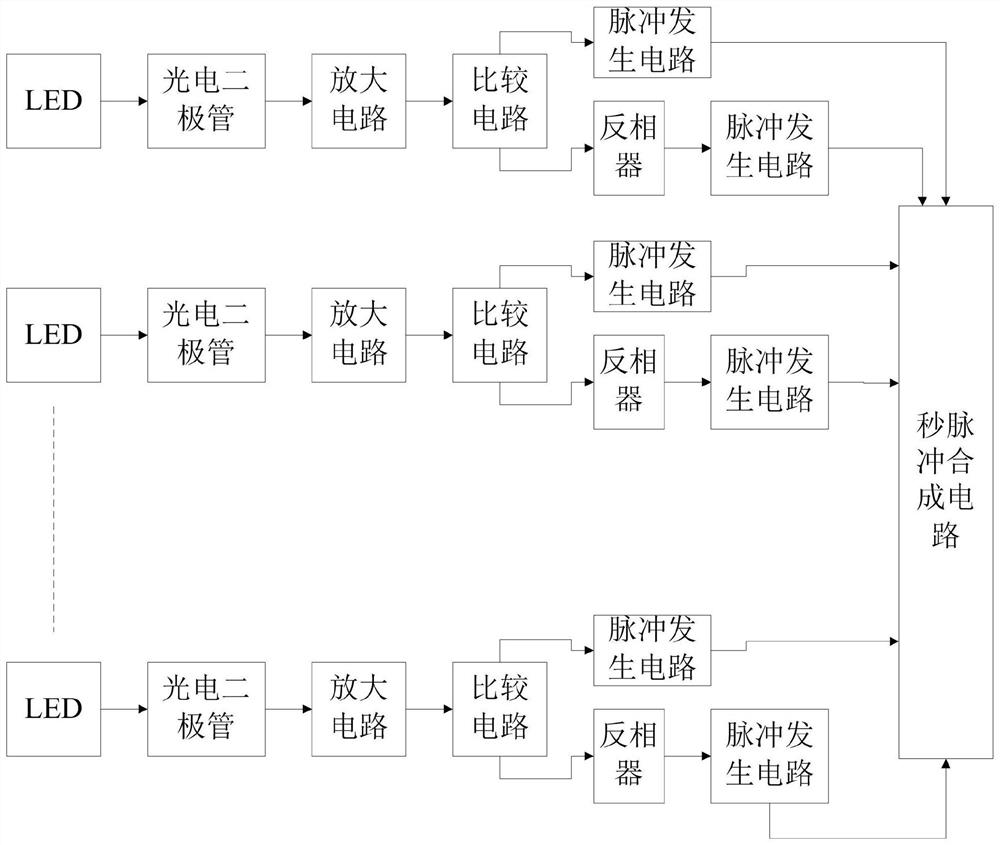
[0045] At present, most digital clocks on the market do not have the second pulse output function, so it is impossible to detect the time difference below the second level of the digital clock. In order to realize the measurement of the time difference below the second level of the digital clock, this embodiment is used to provide a Second pulse generator for digital clock. Such as figure 1 As shown, the second pulse generating device includes a photodiode, an amplifier circuit, a comparison circuit, a pulse generating circuit and a second pulse synthesis circuit;
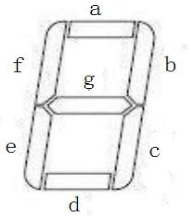
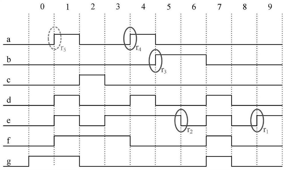
[0046]At least three segments of LEDs included in the digital clock's second digital tube are respectively connected to one of the photodiodes; the photodiodes are used to collect the on-off signals of the LEDs connected to them, and output corresponding The current signal of the current signal; the wavelength of the LED used in the digital clock is generally below 700nm, and the photodiode can be a PIN silicon ph...
Embodiment 2
[0081] This embodiment is used to provide a method for generating second pulses of a digital clock, using the device for generating second pulses of a digital clock described in Embodiment 1 to work, such as Figure 10 Shown, described second pulse generation method comprises the steps:
[0082] Step 101: Use the photodiode to collect the on-off signal of the LED connected to it, output the corresponding current signal according to the on-off signal and transmit it to the amplification circuit; the photodiode is placed above the LED to control the on-off signal of the LED Perform real-time detection.
[0083] Step 102: Using the amplifying circuit to convert the current signal into a voltage signal, and transmitting the voltage signal to a comparison circuit;
[0084] Step 103: Using a comparison circuit to compare the voltage signal with a preset voltage, and output a TTL level signal according to the comparison result; the TTL level signal is divided into two paths, one pat...
Embodiment 3
[0089] This embodiment is used to provide a measurement system for a digital clock, such as Figure 11 As shown, the measurement system includes the second pulse generating device described in Embodiment 1, a reference time frequency source and a time interval measuring instrument;
[0090] The second pulse generating device is connected with the digital clock and the time interval measuring instrument respectively; the second pulse generating device is arranged on the top of the digital clock display unit second position nixie tube; the second pulse generating device is used for The digital clock detects, outputs the second pulse signal corresponding to the digital clock, and transmits the second pulse signal to the time interval measuring instrument;
[0091] The reference time frequency source is connected to the time interval measuring instrument; the reference time frequency source is used to generate a reference time signal, and transmit the reference time signal to the ...
PUM
 Abstract
Description
Claims
Application Information
 - R&D
- Intellectual Property
- Life Sciences
- Materials
- Tech Scout
- Unparalleled Data Quality
- Higher Quality Content
- 60% Fewer Hallucinations
Browse by: Latest US Patents, China's latest patents, Technical Efficacy Thesaurus, Application Domain, Technology Topic, Popular Technical Reports.
© 2025 PatSnap. All rights reserved.Legal|Privacy policy|Modern Slavery Act Transparency Statement|Sitemap|About US| Contact US: help@patsnap.com


