
Eureka
For R&D, Eureka makes reading and utilizing patents & technical documents easy.
Eureka AIR
Designed for self-driven R&D workflows. Generate viable solutions, solve complex R&D challenges, empower your innovation with AI.

Eureka Materials
Designed for material experts only. Revolutionize your material R&D, from search, analyze, to developing new materials.

TechResearch
Generate reliable direction feasibility study reports for your R&D in just a few steps.

TechSeek
Discover and master advanced knowledge NOW. Basics, ideas, possibilities, all at once.

TechMind
As an expert in R&D Theories, TechMind can generates customized viable solutions instantly.

TechRisk
Analyze your overall solution with one click, know your potential R&D risks in advance.

TechMonitor
Get weekly tech updates, stay abreast of the latest tech innovations and key insights.
Cross-shaped notching machine for making preserved kumquats
A technology of cutting machine and cross, which is applied in the field of cross cutting machine, can solve the problems of low work efficiency and labor, and achieve the effect of high work efficiency
- Summary
- Abstract
- Description
- Claims
- Application Information
AI Technical Summary
Problems solved by technology
Method used
Image

Examples
Embodiment 1
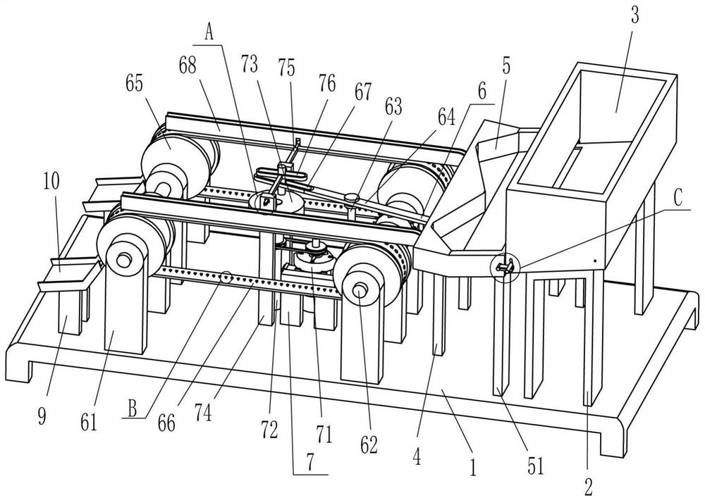
[0024] A kind of kumquat candied fruit making cross cutting machine, such as figure 1 , figure 2 , image 3 and Figure 5 As shown, it includes a base 1, an n-type plate 2, a charging frame 3, a support rod 4, a discharge frame 5, a limit rod 51, a conveying mechanism 6 and a notch mechanism 7, and the top right side of the base 1 is fixed symmetrically front and back. N-type plate 2, a charging frame 3 is fixedly connected between the outer tops of the n-type plates 2 on the front and rear sides, the lower part of the left side of the charging frame 3 is open, and the front and rear symmetrically fixed limit rods 51 are fixed on the right side of the top of the base 1, The limit rod 51 is located on the left side of the n-type plate 2, and the top right side of the base 1 is symmetrically fixed with the support rod 4, and the support rod 4 is located on the left side of the limit rod 51. There is a discharge frame 5, the left and rear parts of the discharge frame 5 are op...
Embodiment 2
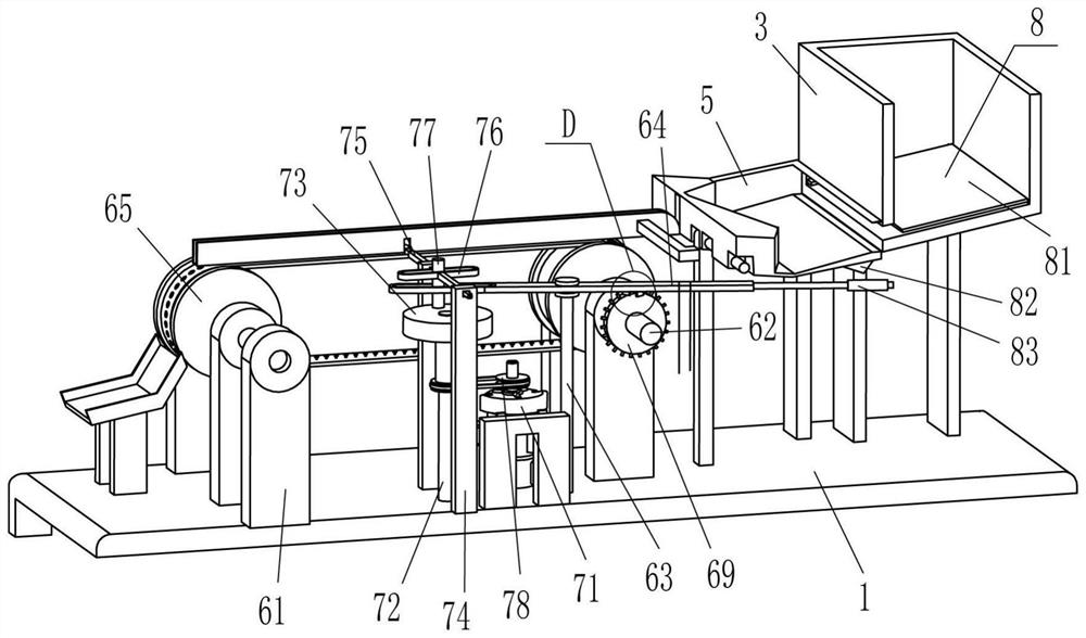
[0031] On the basis of Example 1, such as figure 1 , figure 2 and Figure 4 As shown, swing mechanism 8 is also included, and swing mechanism 8 includes swing plate 81, special-shaped block 82, trigger rod 83, contact block 84 and guide rod 85, and the right end of swing rod 64 is fixedly connected with trigger rod 83, and the discharge frame 5 There is a special-shaped block 82 fixed in the middle of the right side of the outer bottom, and the special-shaped block 82 cooperates with the trigger lever 83. A swing plate 81 is connected in a rotational manner between the front and back sides of the right side of the charging frame 3, and the swing plate 81 is connected to the charging frame 3. Inner fit, the lower sides of the left side of the front and rear sides of the charging frame 3 are slidably connected with guide rods 85, and the inner ends of the guide rods 85 on the front and rear sides are fixedly connected with the left sides of the front and rear sides of the swin...
Embodiment 3
[0034] On the basis of embodiment 1 and embodiment 2, such as figure 1 and Figure 6 As shown, it also includes a fixed plate 9 and a receiving frame 10. The front and rear sides of the top left side of the base 1 are symmetrically fixed with the fixed plate 9, and the receiving frame 10 is fixed between the tops of the two fixed plates 9 on each side. , the receiving frame 10 is located at the left bottom of the left conveying wheel 65 .
[0035] Also comprise push rod 11 and spring 12, on the belt conveyor belt 66, the evenly spaced sliding type piercing is connected with push rod 11, and the hole of push rod 11 is matched with the hole of belt conveyor belt 66, and the inner end of push rod 11 and belt hole A spring 12 is wound between the inner surfaces of the conveyor belt 66 .
[0036] When the cumquat fell from the perforated conveyor belt 66, the cumquat fell into the receiving frame 10, and the cumquat in the receiving frame 10 fell into the collection container. I...
PUM
 Abstract
Description
Claims
Application Information
 - R&D Engineer
- R&D Manager
- IP Professional
- Industry Leading Data Capabilities
- Powerful AI technology
- Patent DNA Extraction
Browse by: Latest US Patents, China's latest patents, Technical Efficacy Thesaurus, Application Domain, Technology Topic, Popular Technical Reports.
© 2024 PatSnap. All rights reserved.Legal|Privacy policy|Modern Slavery Act Transparency Statement|Sitemap|About US| Contact US: help@patsnap.com