Production process of protective film

A production process and protective film technology, applied in the field of protective film production, can solve problems such as low efficiency, complex structure, difficult operation, etc., and achieve the effect of convenient use, simple structure and convenient operation

Inactive Publication Date: 2021-01-19
惠州市国鹏科技有限公司
View PDF0 Cites 1 Cited by
  • Summary
  • Abstract
  • Description
  • Claims
  • Application Information

AI Technical Summary

Problems solved by technology

[0002] Due to the widespread use of protective films in today's production and life, there are certain requirements for some protective film production equipment in the market; however, the existing protective film production equipment has complex structures and difficult operations, and most of them require multiple The use of the staff increases the burden on the staff. Most of the existing protective film production equipment cannot conduct intermittent and quantitative material guidance, which affects the production efficiency of the protective film. Most of the existing protective film production equipment adopts the method of improving the movement of the protective film. To cool and form the protective film, the efficiency is low and the wind in the horizontal direction tends to make the protective film uneven in thickness, which affects the use, and most of the existing protective film production settings do not have an adjustable cutting mechanism, which affects the production of different products. It is inconvenient to cut the protective film of different sizes. Therefore, it is necessary to invent a protective film production equipment and its technological process at this stage.

Method used


Image

  • Production process of protective film
  • Production process of protective film
  • Production process of protective film

Examples


Embodiment Construction

[0038] The following will clearly and completely describe the technical solutions in the embodiments of the present invention with reference to the accompanying drawings in the embodiments of the present invention. Obviously, the described embodiments are only some, not all, embodiments of the present invention. Based on the embodiments of the present invention, all other embodiments obtained by persons of ordinary skill in the art without making creative efforts belong to the protection scope of the present invention.

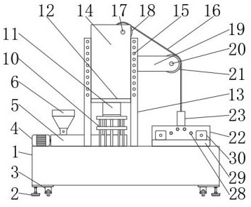
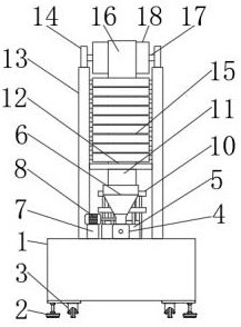
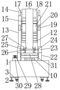
[0039] see Figure 1-6 , the present invention provides a technical solution: the production process of the protective film, including step 1, blown film processing; step 2, printing; step 3, detection; step 4, size cutting; step 5, winding packaging;

[0040] Wherein in above-mentioned step one, blown film processing comprises;

[0041] 1) Manually introduce the protective film substrate particles into the feed hopper 6;

[0042] 2) Start the second motor 8...


PUM


Abstract

The invention discloses a production process of a protective film. A film blowing processing device comprises a first motor, a melt extruder, a feeding hopper, a second motor, a guide plate, a film blowing machine, a rack, a first limiting plate, a heat absorption pipe, a protective film, a first rotating shaft, a first rotating wheel, a supporting plate, a second rotating shaft, a second rotatingwheel, a second limiting plate, a third limiting plate, a connecting shaft, a shearing base, bolts, cutters, a guide wheel, a third motor and a receiving wheel. The production process is simple in structure and convenient to operate, through cooperation of the melting feeding hopper, the second motor and the guide plate, the structure is simple, use is convenient, and the purpose of automatic quantitative material guide is achieved; through cooperation of the rack and the heat absorption pipe, the structure is simple, and the purpose of rapid cooling forming of protective films is achieved; and through cooperation of the connecting shaft, the shearing base, the bolts, the cutters, the third motor and the receiving wheel, the structure is simple, and the purpose of automatically cutting protective films of different sizes is achieved by adjusting the distance between the cutters.

Description

technical field [0001] The invention relates to the technical field of protective film production, in particular to a production process flow of the protective film. Background technique [0002] Due to the widespread use of protective films in today's production and life, there are certain requirements for some protective film production equipment in the market; however, the existing protective film production equipment has complex structures and difficult operations, and most of them require multiple The use of the staff increases the burden on the staff. Most of the existing protective film production equipment cannot conduct intermittent and quantitative material guidance, which affects the production efficiency of the protective film. Most of the existing protective film production equipment adopts the method of improving the movement of the protective film. To cool and form the protective film, the efficiency is low and the wind in the horizontal direction tends to mak...

Claims


Application Information

Patent Timeline
IPC IPC(8): B29C55/28B29C35/16B29C48/28B29C48/285
CPCB29C35/16B29C55/28B29C48/0017B29C48/0022B29C48/0023B29C48/28B29C48/288
Inventor 刘瑞富
Owner 惠州市国鹏科技有限公司
Why Eureka
Try Eureka