Eureka AIR delivers breakthrough ideas for toughest innovation challenges, trusted by R&D personnel around the world.

Petroleum pipeline supporting base capable of being automatically adjusted

An oil pipeline, automatic adjustment technology, applied in the direction of pipeline supports, pipe components, pipes/pipe joints/pipe fittings, etc., can solve the problems of increasing the workload of staff, inconvenient disassembly and installation of fixed structures, and unfavorable oil pipeline laying efficiency. To achieve the effect of increasing efficiency and enhancing the degree of fixation

Inactive Publication Date: 2021-01-19
钟露
View PDF2 Cites 10 Cited by
  • Summary
  • Abstract
  • Description
  • Claims
  • Application Information

AI Technical Summary

Problems solved by technology

[0006] The existing device can play a shockproof effect on the oil pipeline, but the device is limited by the way it is connected to the ground. When using the existing device to fix the oil pipeline, the staff need to fix the device on the ground before proceeding. For the installation of oil pipelines, in order to avoid the tightness of the joints of oil pipelines, it is necessary to have an extremely accurate estimate of the path of oil pipeline laying, which greatly increases the technical requirements for the workers who lay oil pipelines, otherwise frequent Pull out the device and move it to coordinate the position. However, the disassembly and installation of the fixed structure between the existing device and the ground are very inconvenient, which greatly increases the workload of the staff and is not conducive to improving the efficiency of laying oil pipelines. In view of this, we propose a self-adjusting oil pipeline support seat

Method used


Image

  • Petroleum pipeline supporting base capable of being automatically adjusted
  • Petroleum pipeline supporting base capable of being automatically adjusted
  • Petroleum pipeline supporting base capable of being automatically adjusted

Examples


Embodiment Construction

[0031] In describing the present invention, it should be understood that the terms "center", "longitudinal", "transverse", "length", "width", "thickness", "upper", "lower", "front", " Orientation indicated by rear, left, right, vertical, horizontal, top, bottom, inside, outside, clockwise, counterclockwise, etc. The positional relationship is based on the orientation or positional relationship shown in the drawings, and is only for the convenience of describing the present invention and simplifying the description, rather than indicating or implying that the referred device or element must have a specific orientation, be constructed and operated in a specific orientation, Therefore, it should not be construed as limiting the invention.

[0032] In the description of the present invention, "plurality" means two or more, unless otherwise specifically defined.

[0033] In the description of the present invention, it should be noted that, unless otherwise specified and limited, t...


PUM


Abstract

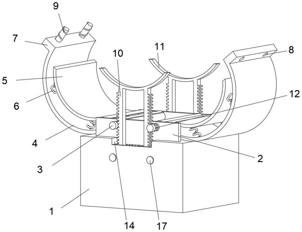
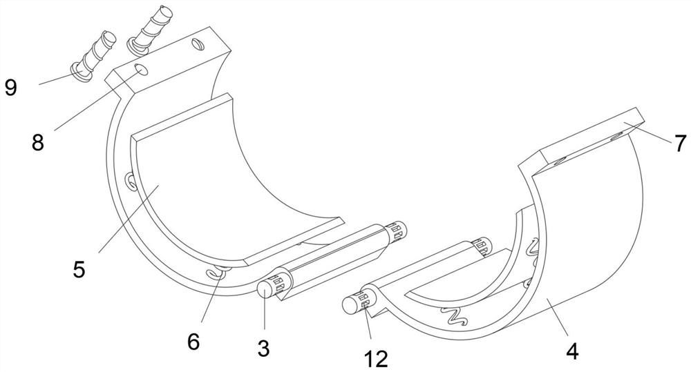
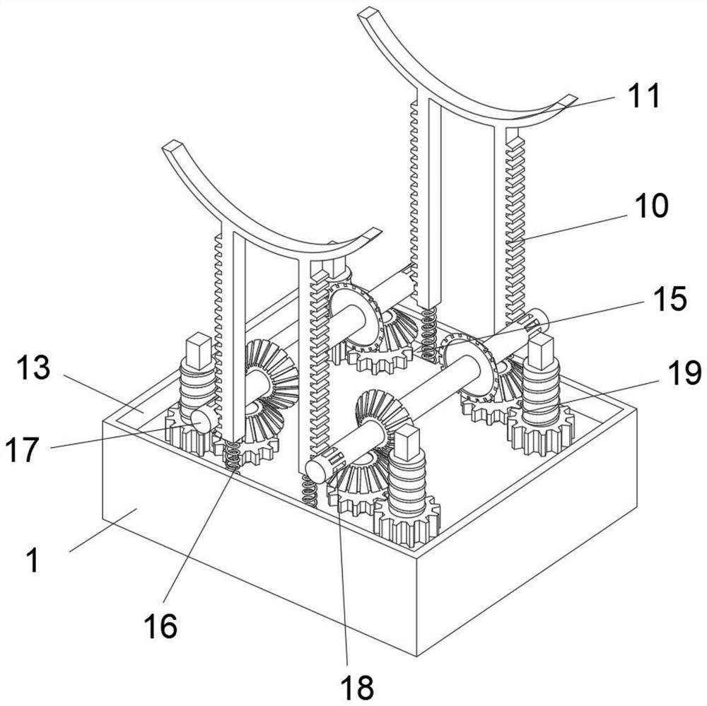
The invention discloses a petroleum pipeline supporting base capable of being automatically adjusted, and belongs to the technical field of petroleum pipeline supporting. The petroleum pipeline supporting base capable of being automatically adjusted comprises a base, wherein two side plates are fixedly arranged on the top face of the base in a symmetrical structure; two rotating shafts A are symmetrically arranged between the two side plates in a penetrating mode; arc-shaped plates are connected to the middles of the rotating shafts A in a sleeving mode; two racks are arranged on the outer sides of the side plates in a symmetrical structure; a supporting plate is fixedly arranged between the top faces of the two racks; a plurality of tooth grooves A are annularly formed in the positions, relative to the racks, of the outer walls of the rotating shafts A at equal intervals; the interior of the base is hollow to form a cavity; two rotating shafts B are symmetrically arranged in the middle of the cavity in a penetrating mode; a plurality of tooth grooves B are annularly formed in the positions, relative to the racks, of the outer walls of the rotating shafts B at equal intervals; andtwo fixing assemblies are symmetrically arranged on the front sides and the rear sides of the rotating shafts B. According to the petroleum pipeline supporting base, the convenience degree of petroleum pipeline laying is improved, the fixing firmness of a petroleum pipeline is also enhanced, double purposes are achieved at one stroke, and convenience and rapidness are achieved.

Description

technical field [0001] The invention relates to the technical field of oil pipeline support, in particular to an automatically adjustable oil pipeline support base. Background technique [0002] Petroleum transportation needs to use oil pipelines, and in the process of laying oil pipelines, it is necessary to use oil pipeline support seats to support and fix them. Most of the existing support seats cannot automatically respond to the diameter specifications of oil pipelines. Adjustment, which has caused inconvenience in the production of the support seat. [0003] After retrieval, the patent with the publication number CN208074276U discloses a fixing device for an oil pipeline support seat. The device is installed on the ground through a fixing hole, and the oil pipeline is placed between the upper fixing ring and the lower fixing ring and the upper pressing plate The lower pressing plate is locked by fixing bolts, thus making up for the inconvenient disassembly phenomenon ...

Claims


Application Information

Patent Timeline
IPC IPC(8): F16L3/10F16L3/205F16L55/035
CPCF16L3/1075F16L3/205F16L55/035
Inventor 钟露
Owner 钟露
Why Eureka
Eureka Blog
Learn More