Dehumidifier

A dehumidifier and airframe technology, applied in mechanical equipment, engine components, engine sealing, etc., can solve problems such as complex structure of water leakage prevention devices, achieve the effects of simple installation, avoid water leakage problems, and low production costs

Active Publication Date: 2021-01-19
TCL德龙家用电器(中山)有限公司
View PDF7 Cites 1 Cited by
  • Summary
  • Abstract
  • Description
  • Claims
  • Application Information

AI Technical Summary

Problems solved by technology

[0004] The main purpose of the present invention is to provide a dehumidifier, which aims to solve the

Method used


Image

  • Dehumidifier
  • Dehumidifier
  • Dehumidifier

Examples


Example Embodiment

[0037] The technical solutions in the embodiments of the present invention will be clearly and completely described below with reference to the accompanying drawings in the embodiments of the present invention. Obviously, the described embodiments are only a part of the embodiments of the present invention, not all of the embodiments. Based on the embodiments of the present invention, all other embodiments obtained by those of ordinary skill in the art without creative work fall within the protection scope of the embodiments of the present invention.

[0038] It should be noted that all directional indications (such as up, down, left, right, front, back, etc.) in the embodiments of the present invention are only used to explain the relationship between various components under a certain posture (as shown in the accompanying drawings). The relative positional relationship, the movement situation, etc., if the specific posture changes, the directional indication also changes acco...


PUM


Abstract

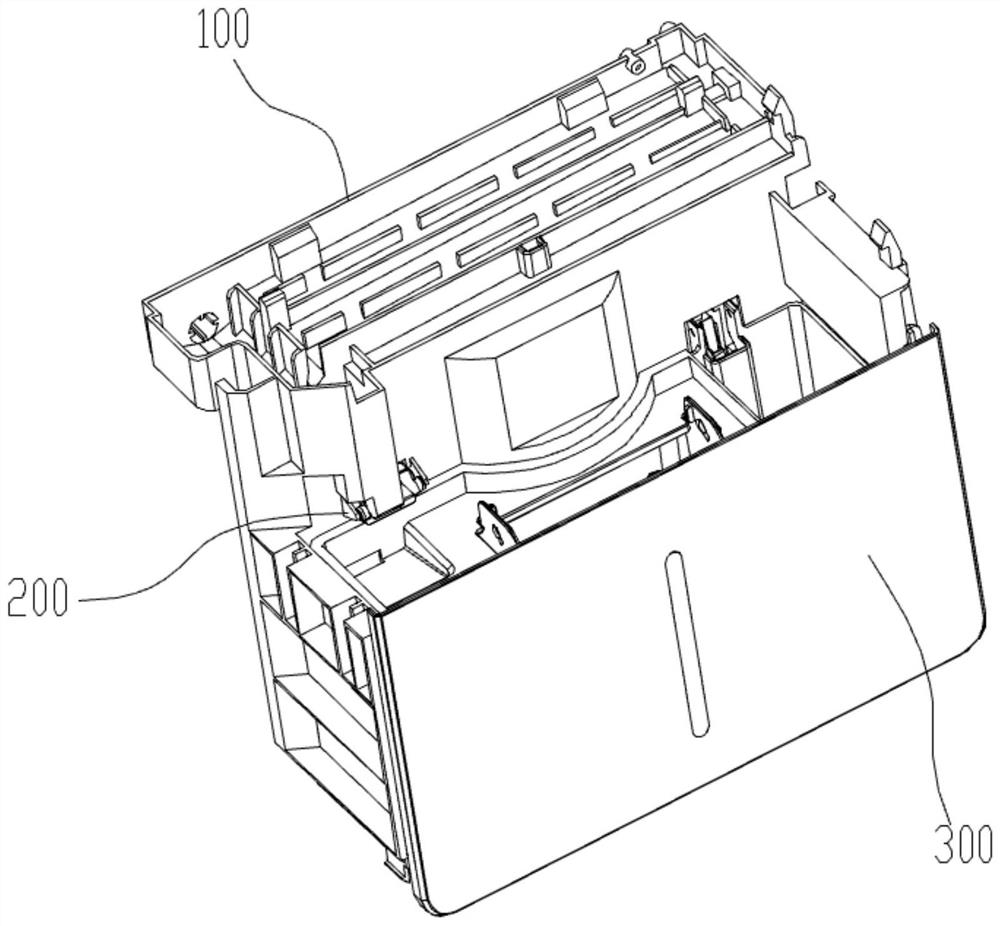
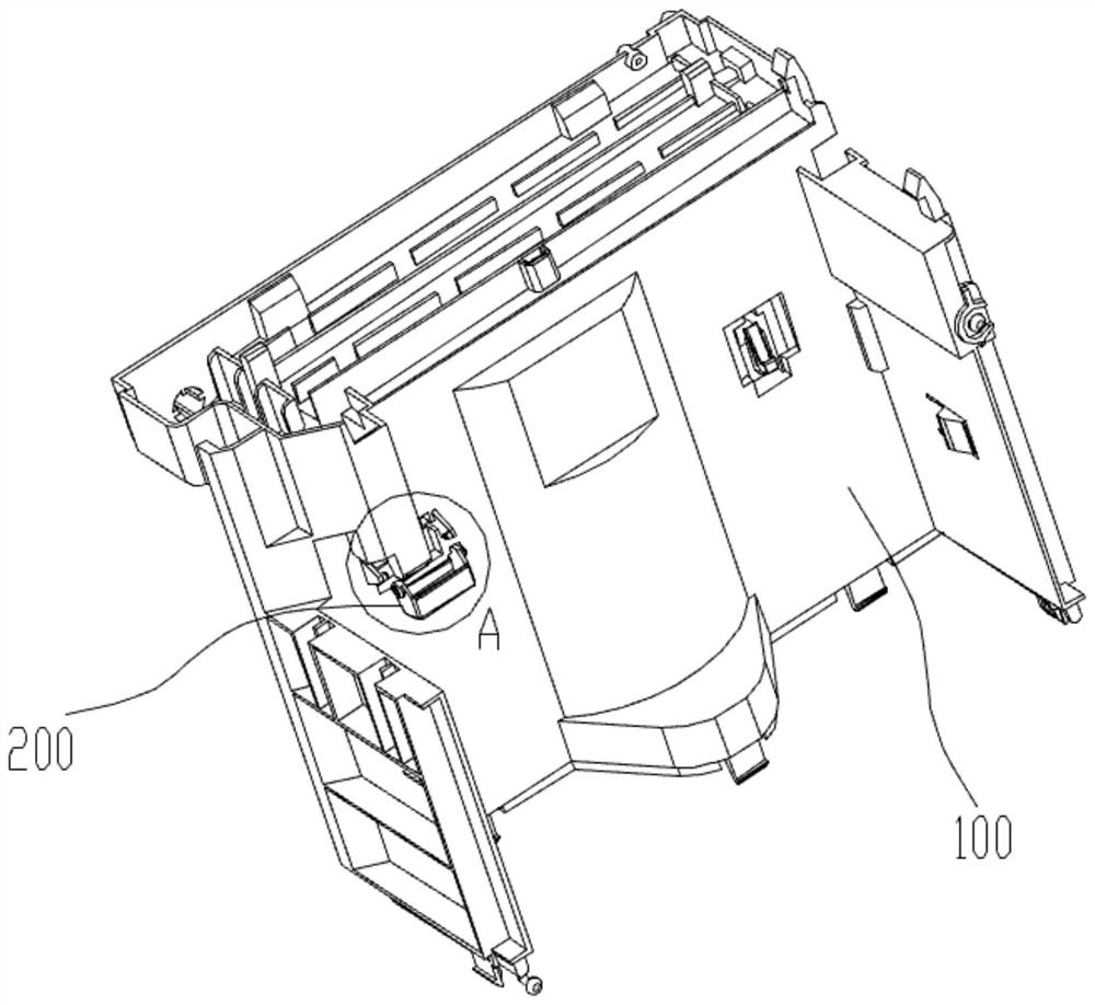
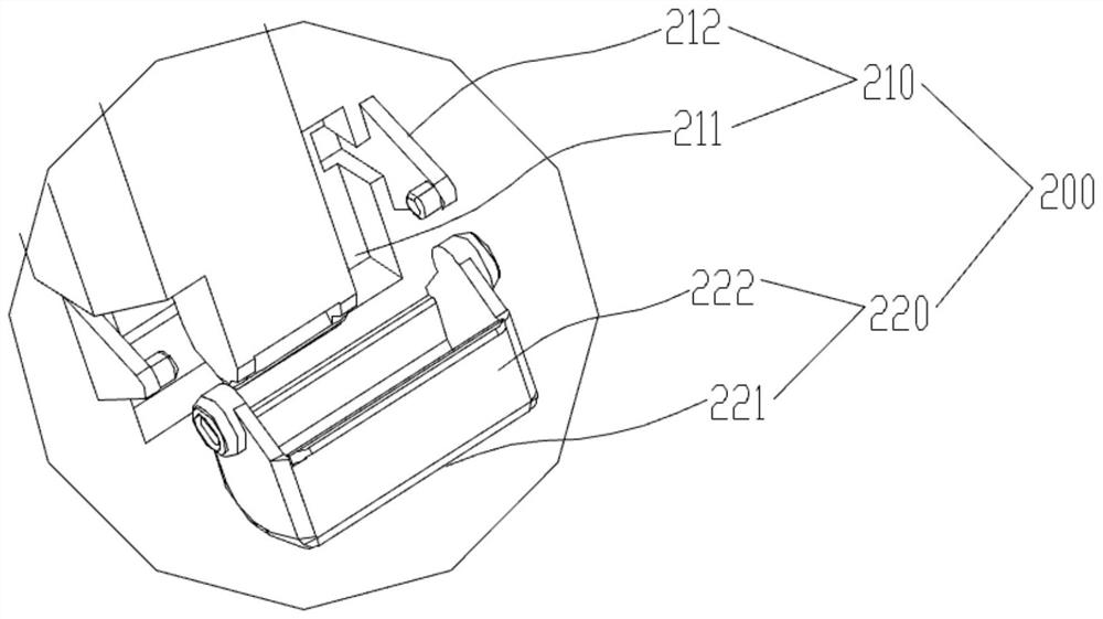
The invention discloses a dehumidifier. The dehumidifier comprises a machine body and a water receiving piece. The machine body is provided with a water outlet used for guiding out condensate water. The water receiving piece is rotationally connected with the machine body, and the water receiving piece is provided with a first position located below the water outlet and a second position located on one side of the water outlet. The dehumidifier solves the technical problem that a water leakage prevention device in an existing dehumidifier is complex in structure.

Description

technical field [0001] The invention relates to the field of dehumidifiers, in particular to a dehumidifier. Background technique [0002] A dehumidifier uses a fan to draw humid air into the fuselage, condenses the water molecules in the air into water droplets through heat exchange and other means, and discharges the treated dry air out of the fuselage, so that the dehumidifier in a certain space Electrical appliances that keep the air humidity within an appropriate range. [0003] When the dehumidifier is working, the condensed water formed by the evaporator gathers in the water receiving tray and flows into the water tank along the waterway through the drain port. To the chassis or the ground, affecting the user's use. At present, an anti-leakage device is usually added to the dehumidifier to prevent condensed water from flowing on the ground, but the existing anti-leakage device has a complex structure and the effect of preventing water leakage is not ideal. Content...

Claims


Application Information

Patent Timeline
IPC IPC(8): F24F3/14F24F13/22F24F13/20F16J15/02
CPCF24F3/14F24F13/222F24F13/20F16J15/02F24F2003/144
Inventor 张博翔胡思培李上保潘啟裔李伟标陶孙华
Owner TCL德龙家用电器(中山)有限公司
Why Eureka
Try Eureka