Binding machine

A technology of binding machine and binding wire, which is applied in the fields of application, cultivation, agriculture, etc. It can solve the problems of high steel wire specifications, complex internal structure, and poor overall versatility, and achieve the effect of improving binding efficiency, simplifying structure, and fast binding

Pending Publication Date: 2021-01-22
NINGBO XINYI WEIYE IMPORT & EXPORT CO LTD
View PDF0 Cites 1 Cited by
  • Summary
  • Abstract
  • Description
  • Claims
  • Application Information

AI Technical Summary

Problems solved by technology

[0002] The vines need to be attached to the fixed object to grow, but in the event of strong wind and heavy rain, if there is no extra fixation, the vines will be easily blown down
[0003] At present, vines and fixed brackets are often tied together with ropes or wires to fix the vines, but the manual binding of the ties is time-consuming and inefficient; and the previously designed tying machines require metal wires with special shapes and structures to fix the vines. Binding, some equipment similar to binding steel bars on the construction site has insufficient shearing power, high requirements for the diameter of the steel wire used for binding, and poor overall versatility; and the internal structure is complex and the transmission efficiency is low. Therefore, it is necessary to design a machine that can Fast binding of vines, simple internal structure, high transmission efficiency and universal binding machine, not limited to the specific structural shape of the metal wire

Method used


Image

  • Binding machine
  • Binding machine
  • Binding machine

Examples


Embodiment 1

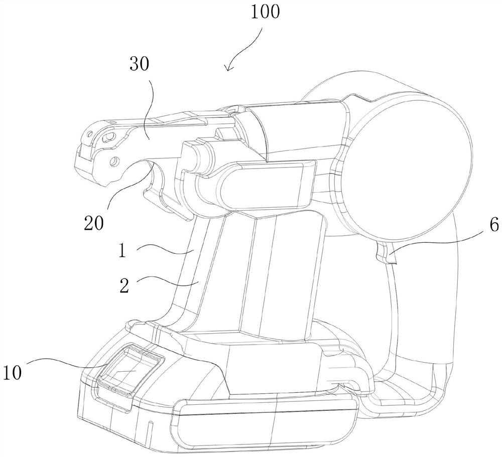
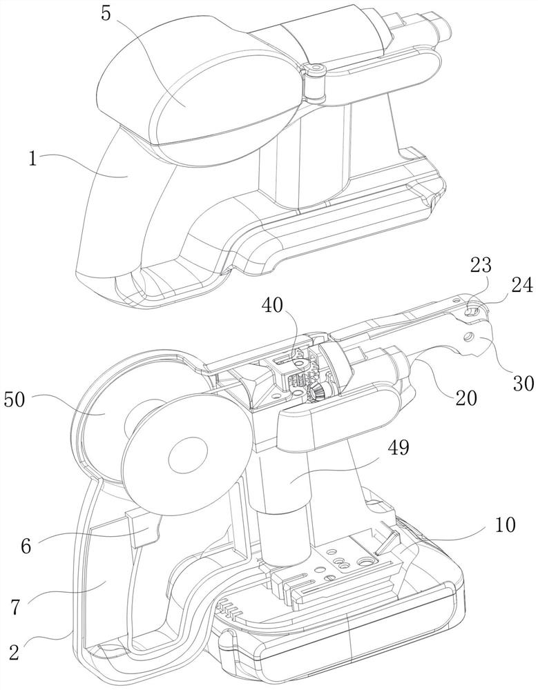
[0046] see figure 1 and figure 2 , a strapping machine 100 including a driving part 49 , a cutting part 30 , a transmission part 40 and a strapping part 20 .

[0047] Specifically, the transmission part 40, the transmission part 40 is driven by the driving part 49, and the binding wire is driven by the transmission part 40 to move to the binding part 20; The binding coil is formed; the cutting part 30 is connected with the transmission part 40 in transmission, and the binding coil is cut off from the binding line through the cutting part 30 . The binding part can quickly bind the plants and vines, and the set binding part can change the conveying path of the binding wire, so that the binding wire used for binding can be automatically wound around the surface of the vines in the form of a ring to realize binding; greatly improved The binding efficiency reduces the labor intensity of people; the cutting part set can quickly cut the binding line, which improves the work effici...

Embodiment 2

[0049] This embodiment is a further optimization scheme on the basis of embodiment 1:

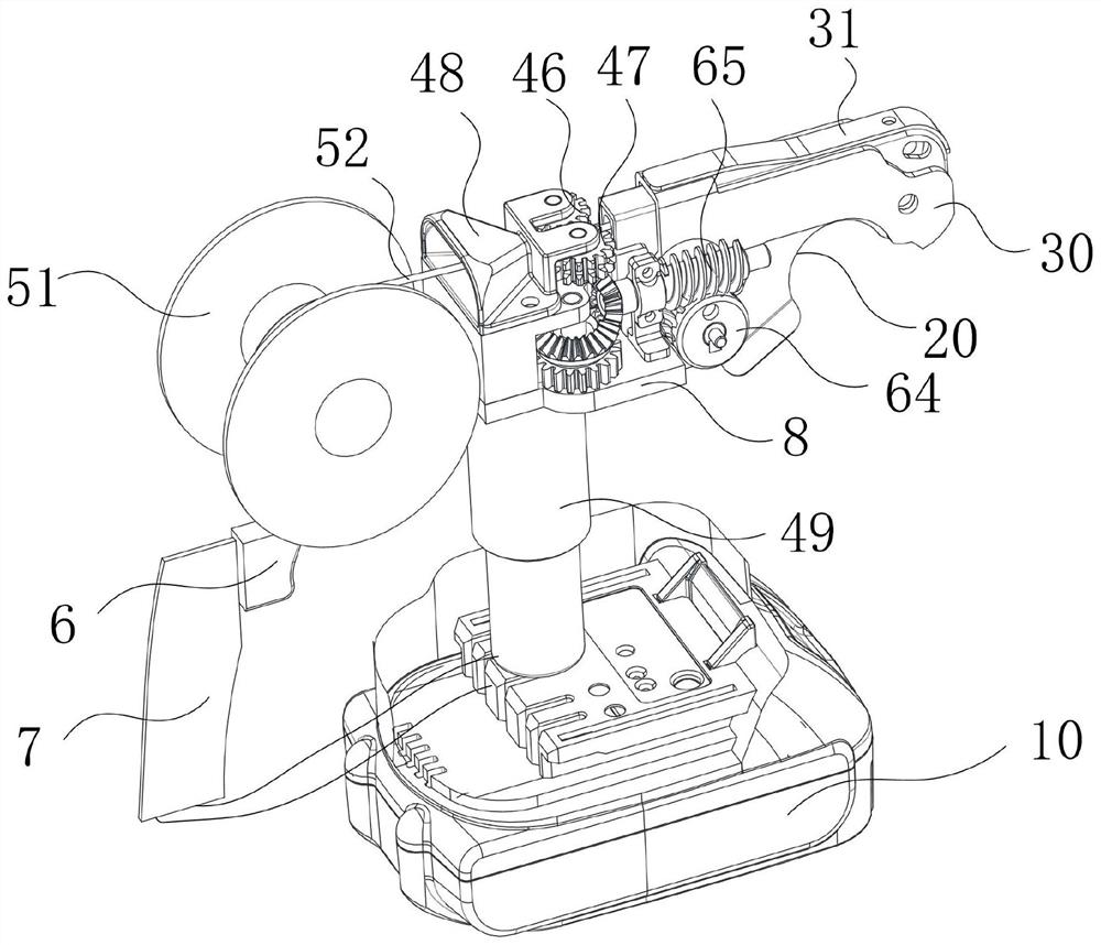
[0050] see Figure 4 , the driving part 49 can drive the transmission part 40 to rotate forward or reversely. When the transmission part 40 rotates forward, it drives the binding wire to move continuously to the binding part 20; The action cuts the lashing coil from the lashing wire. Through the forward and reverse rotation of the transmission part, the binding part and the shearing part are controlled to complete the binding and cutting actions respectively, which greatly improves the work efficiency, and the transmission mode of the whole transmission part is simple and efficient, which makes the overall structure of the strapping machine more streamlined and convenient. Install.

[0051] Further, see Figure 5 , the driving part 49 includes a power output shaft one 42, and the transmission part 40 includes a driving wheel one 43 and a driving wheel two 61 respectively connected to the...

Embodiment 3

[0058] This embodiment is a further optimization scheme on the basis of embodiment 2:

[0059] Further, see Figure 4 and Figure 5 The shearing part 30 includes a shearing power part (not shown in the figure), and the shearing power part includes a worm 65 , and the worm 65 is in driving connection with a driven wheel 2 63 through a driven wheel 3 62 . It is convenient for the secondary rotation of the driven wheel to drive the rotation of the worm, so as to realize the transmission of force.

[0060] Further, the shearing part comprises a shearing knife 32 and a shearing transmission part 60, the shearing transmission part comprises a transmission housing 33, a shearing power part and a cam 67, and the shearing power part is driven by the shearing transmission part 60 to drive the cam 67 to rotate , thereby driving the transmission housing 33 to move upwards, and then driving the shearing knife 32 to trim the thread. The cam is driven by the shearing power part to provide...


PUM


Abstract

The invention discloses a binding machine. The binding machine comprises a driving part, a transmission part, a binding part and a shearing part. The transmission part is driven by the driving part, and binding and shearing of a binding wire are completed through forward and reverse rotation of the transmission part; the binding part is in transmission connection with the transmission part, and inthe binding part, the binding wire is wound to form a binding coil; and the shearing part comprises a shearing transmission part and a shearing knife which are in transmission connection with the transmission part, and the shearing knife is driven by the shearing transmission part to shear off the binding coil from the binding wire. The binding part can quickly bind plant vines, and the arrangedbinding part can change the conveying path of the binding wire, so that the binding wire used for binding can be automatically wound to form a hanging ring shape to be wound on the surfaces of the vines, and binding is achieved; the binding efficiency is improved, and the labor intensity is reduced; and the arranged shearing part can be used for quickly shearing the binding wire, so that the working efficiency is improved, and the situation that scissors or other sharp edges are manually taken for shearing in the traditional process is avoided.

Description

technical field [0001] The invention relates to the technical field of binding equipment, in particular to a binding machine. Background technique [0002] The vines need to be attached to the fixed object to grow, but in the event of strong wind and heavy rain, if no extra fixation is applied, the vines will easily be blown down. [0003] At present, vines and fixed brackets are often tied together with ropes or wires to fix the vines, but the manual binding of the tying pieces is time-consuming and inefficient; Binding, some equipment similar to bundling steel bars on the construction site has insufficient shear power, high requirements for the diameter of the steel wire used for bundling, and poor overall versatility; and the internal structure is complex and the transmission efficiency is low. Therefore, it is necessary to design a machine that can Fast binding of vines, simple internal structure, high transmission efficiency and universal binding machine, not limited t...

Claims


Application Information

Patent Timeline
Patent Type & Authority Applications(China)
IPC IPC(8): A01G17/08
CPCA01G17/08
Inventor 陈志伟
Owner NINGBO XINYI WEIYE IMPORT & EXPORT CO LTD
Why Eureka
Try Eureka