Egg protection device for pheasant field egg laying
A protection device, field technology, applied in the application, poultry industry, poultry cage or house, etc., to achieve the effect of improving installation efficiency and improving recovery efficiency
- Summary
- Abstract
- Description
- Claims
- Application Information
AI Technical Summary
Problems solved by technology
Method used
Image
Examples
Embodiment 1
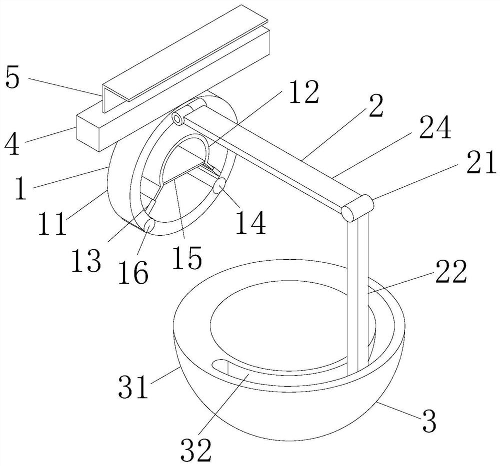
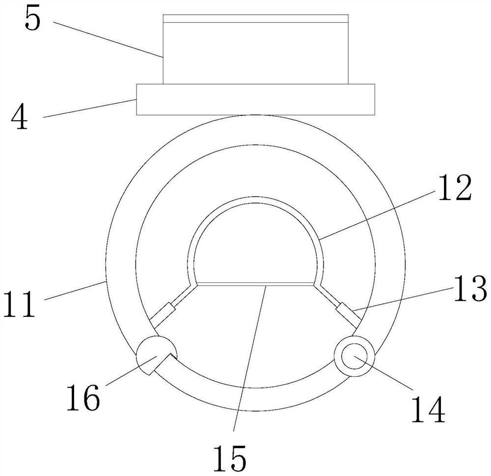
[0025] Example 1: Please refer to figure 1 , egg protection device for wild pheasant eggs, including head connector 1, movable connector 2 and receiving protection device 3, head connector 1 includes main ring 11, connecting shaft 14 and one-way buckle 16, connecting shaft 14 and the one-way buckle 16 are located below the main ring 11, and the one-way buckle 16 and the connecting shaft 14 are located in the upper and lower half of the main ring 11 and arranged symmetrically front and back, and a cross bar 4 is fixedly installed above the head connector 1, and the cross bar 4 There is an L-shaped hanging plate 5 inside the movable card, and the right side of the main ring 11 is provided with a movable connector 2. The movable connector 2 includes a movable shaft 21 and a connecting plate 24. The connecting plate 24 is located at the upper end of the right side of the main ring 11 and the main ring 11 Between use hinge to carry out movable connection, connecting plate 24 is fix...
Embodiment 2
[0026] Embodiment 2: On the basis of Embodiment 1, please refer to figure 1 with image 3 , the head connector 1 also includes a secondary ring 12 and an activator 13, the activator 13 and the secondary ring 12 are both arranged in the main ring 11, and the secondary ring 12 and the main ring 11 are concentric rings, and the activators 13 are respectively Set on both sides of the auxiliary ring 12 front and rear symmetry, the activator 13 is a telescopic column, and the activator 13 is provided with a tension spring, the movable end of the activator 13 is fixedly connected with the auxiliary ring 12, and the fixed end of the activator 13 is connected to the inner wall of the main ring 11 The part between the two movers 13 at the lower end of the auxiliary ring 12 is cut off, and a discharge plate 15 is arranged between the cut off parts of the auxiliary ring 12. The front and rear ends of the discharge plate 15 use magnetic blocks and The openings of the shaved part of the se...
Embodiment 3
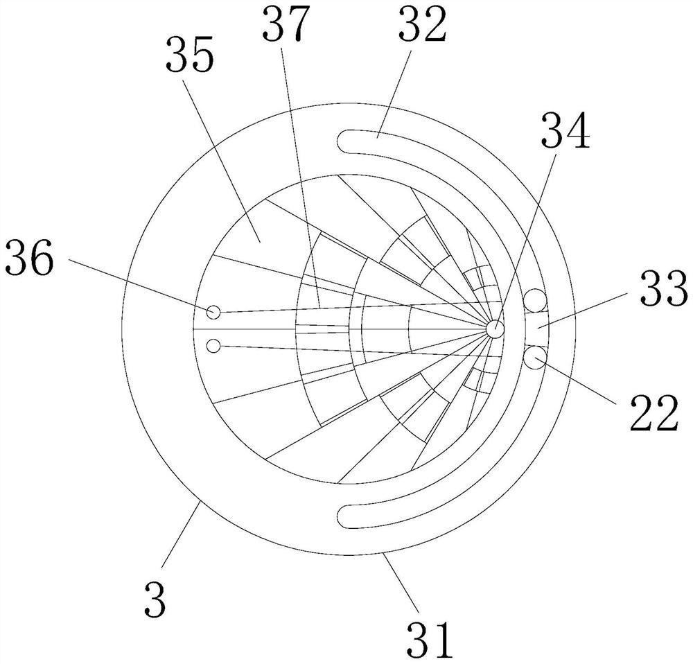
[0027] Embodiment three: on the basis of embodiment two, please refer to figure 2 with Figure 4 The receiving protection device 3 includes a receiving basin 31, which is a hemisphere, and the upper surface of the receiving basin 31 is provided with an installation groove 32, and the installation groove 32 is opened half a circle along the inner edge of the receiving basin 31, and the center of the upper surface of the receiving basin 31 is opened. There is a hemispherical groove smaller than the installation groove 32, the connecting rod 22 is movably inserted in the installation groove 32, and a separation positioning block 33 is arranged between the two connecting rods 22, and the separation positioning block 33 is located at the arc midpoint of the installation groove 32 It is fixedly connected with the inner wall of the installation groove 32, and the connecting rod 22 and the movable shaft 21 are used for movable connection. The parts of the two connecting rods 22 locat...
PUM
 Abstract
Description
Claims
Application Information
 - R&D
- Intellectual Property
- Life Sciences
- Materials
- Tech Scout
- Unparalleled Data Quality
- Higher Quality Content
- 60% Fewer Hallucinations
Browse by: Latest US Patents, China's latest patents, Technical Efficacy Thesaurus, Application Domain, Technology Topic, Popular Technical Reports.
© 2025 PatSnap. All rights reserved.Legal|Privacy policy|Modern Slavery Act Transparency Statement|Sitemap|About US| Contact US: help@patsnap.com


