
Automatic bidirectional clamping drilling machine

A two-way clamping and automatic technology, applied in the direction of clamping, supporting, positioning devices, etc., can solve the problems of reduced work efficiency, reduced precision of workpiece drilling, long operating time, etc., to improve work efficiency and realize precise movement , the effect of simple operation

Pending Publication Date: 2021-01-22
谢东
View PDF1 Cites 8 Cited by
  • Summary
  • Abstract
  • Description
  • Claims
  • Application Information

AI Technical Summary

Problems solved by technology

[0003] The existing drilling machines have the following disadvantages: 1. Most of the existing drilling machines require the operator to operate the clamping mechanism multiple times when clamping the workpiece. There are many operating steps and long operating time, resulting in reduced work efficiency; The mechanism for moving the workpiece in the existing drilling machine is inconvenient to use, and the workpiece is prone to offset when moving, resulting in a decrease in the accuracy of the drilling of the workpiece; 3. Most of the existing drilling machines do not have the function of cleaning residual debris during drilling, and the drilling machine is long After time is used, debris is easy to accumulate inside the drilling machine, which affects the mechanical operation inside the drilling machine; 4. The control structure of the drilling depth in the existing drilling machine is relatively complicated, resulting in the overall structure of the drilling machine is not compact

Method used


Image

  • Automatic bidirectional clamping drilling machine
  • Automatic bidirectional clamping drilling machine
  • Automatic bidirectional clamping drilling machine

Examples


Embodiment Construction

[0032] In order to make the technical means, creative features, goals and effects achieved by the present invention easy to understand, the present invention will be further described below in conjunction with specific embodiments.

[0033] In the description of the present invention, it should be noted that the terms "upper", "lower", "inner", "outer", "front end", "rear end", "both ends", "one end", "another end" The orientation or positional relationship indicated by etc. is based on the orientation or positional relationship shown in the drawings, and is only for the convenience of describing the present invention and simplifying the description, rather than indicating or implying that the referred device or element must have a specific orientation, use a specific Azimuth configuration and operation, therefore, should not be construed as limiting the invention. In addition, the terms "first" and "second" are used for descriptive purposes only, and should not be understood ...


PUM


Abstract

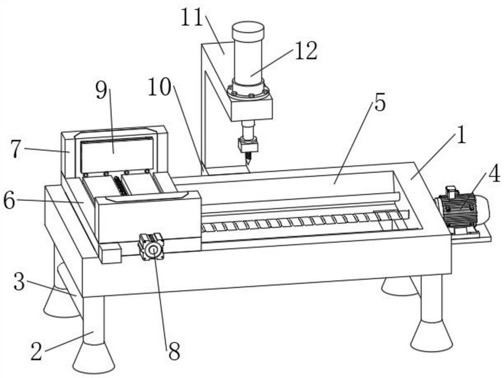
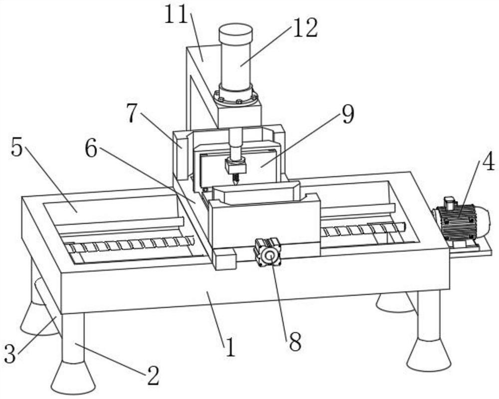
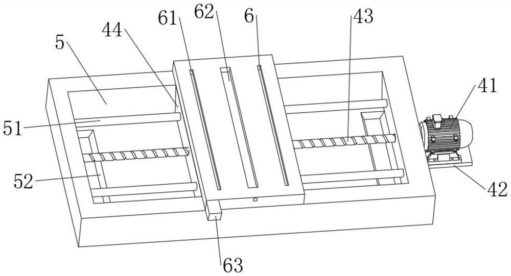
The invention discloses an automatic bidirectional clamping drilling machine. The automatic bidirectional clamping drilling machine comprises a workbench. Two supporting legs are fixedly installed oneach the left portion of the lower end of the workbench and the right portion of the lower end of the workbench, a reinforcing rod is fixedly connected between the every two corresponding supporting legs jointly, a first installing groove is formed in the upper end of the workbench, and a moving mechanism is arranged at the right end of the workbench. A containing table is arranged at the upper end of the workbench, vertical plates are fixedly installed at the front portion and the rear portion of the upper end of the containing table, a clamping mechanism is arranged at the front end of the containing table, automatic stopping mechanisms are arranged at the ends, close to each other, of the two vertical plates, and a connecting block is fixedly installed in the middle of the rear end of the workbench. An L-shaped arm is fixedly installed at the rear portion of the upper end of the connecting block, a drilling mechanism is arranged at the upper end of the L-shaped arm, and the drillingmechanism extends to the position above the first installing groove. The automatic bidirectional clamping drilling machine is compact in structure, capable of automatically clamping and fixing a workpiece, high in drilling precision, high in practicability and convenient to use.

Description

technical field [0001] The invention relates to the technical field of drilling machine equipment, in particular to a drilling machine with automatic bidirectional clamping. Background technique [0002] Drilling machine refers to a machine tool that mainly uses a drill bit to process holes in a workpiece. Generally, the rotation of the drill bit is the main movement, and the axial movement of the drill bit is the feed movement. The drilling machine has a simple structure and relatively low machining accuracy. It can drill through holes and blind holes, replace special tools, expand, countersink, ream or tap. During the machining process, the workpiece does not move, let the tool move, align the center of the tool with the center of the hole, and make the tool rotate (main movement). The characteristic of the drilling machine is that the workpiece is fixed and the tool rotates. [0003] The existing drilling machines have the following disadvantages: 1. Most of the existi...

Claims


Application Information

Patent Timeline
Patent Type & Authority Applications(China)
IPC IPC(8): B23Q3/06B23Q5/28B23Q5/40B23Q17/24
CPCB23Q3/062B23Q5/40B23Q5/28B23Q17/24B23Q17/2447
Inventor 谢东
Owner 谢东
Learn More