
An anti-fatigue power connection structure for lifting charging pile

A technology for power connection and charging pile, applied in the field of anti-fatigue power connection structure for lift-type charging piles, can solve the problems of affecting the charging efficiency of the charging pile, poor heat dissipation of the power cord, and short service life of the power cord, etc. Improve heat dissipation efficiency and ensure the effect of normal work

Active Publication Date: 2022-02-11
国网商用电动汽车投资有限责任公司
View PDF0 Cites 0 Cited by
  • Summary
  • Abstract
  • Description
  • Claims
  • Application Information

AI Technical Summary

Problems solved by technology

[0004] The purpose of the present invention is to solve the short service life of the power line of the traditional lifting charging pile in the prior art, and at the same time, the poor heat dissipation of the power line also affects the charging efficiency of the charging pile. A lifting type charging pile is proposed. Anti-fatigue power connection structure for charging pile

Method used


Image

  • An anti-fatigue power connection structure for lifting charging pile
  • An anti-fatigue power connection structure for lifting charging pile
  • An anti-fatigue power connection structure for lifting charging pile

Examples


Embodiment 1

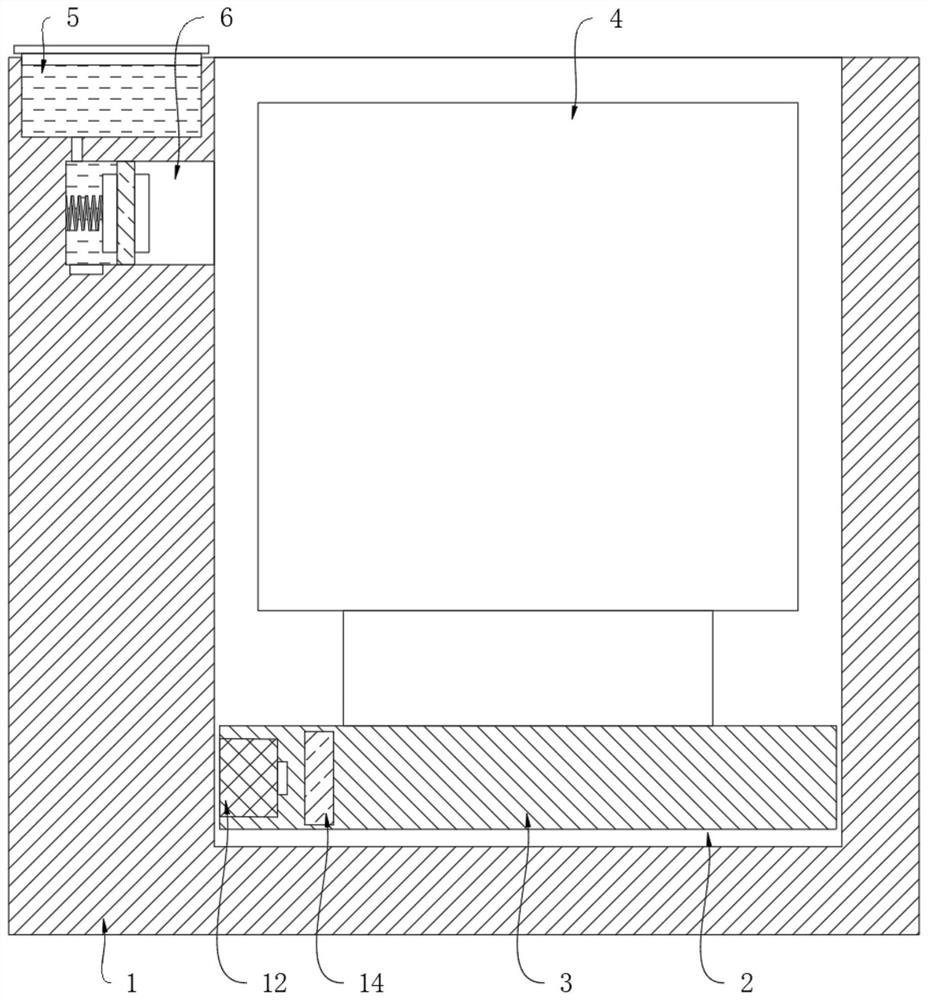
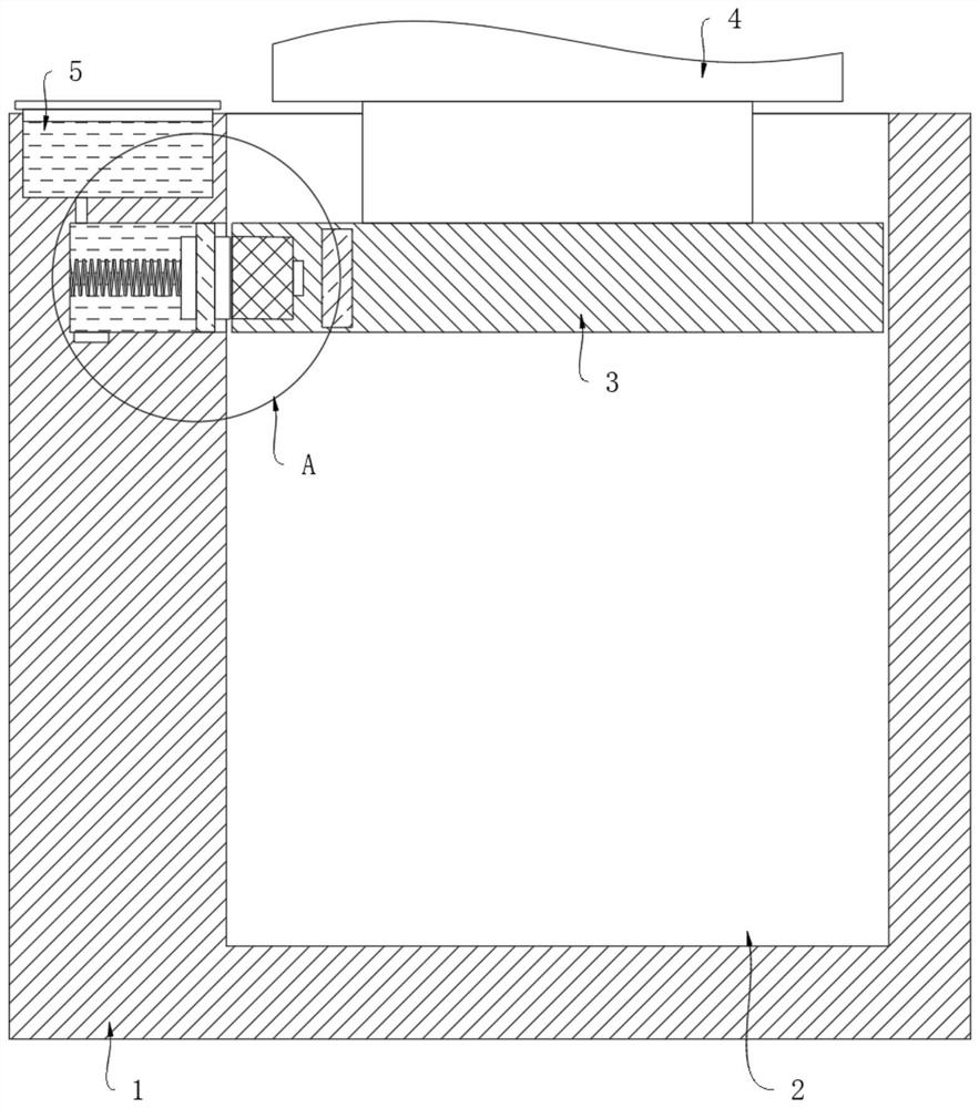
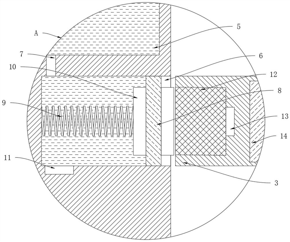
[0021] refer to Figure 1-3 , an anti-fatigue power connection structure for a lifting charging pile, including a foundation 1 and a charging pile body 4, a storage tank 2 is opened in the foundation 1, and a load-bearing plate 3 for placing the charging pile body 4 is sealed and slidably connected in the storage groove 2 , a drive device is provided between the load-bearing plate 3 and the storage tank 2, the drive device is a telescopic cylinder, and the telescopic cylinder is installed on the inner bottom wall of the storage tank 2, and the output end of the telescopic cylinder is fixedly connected with the lower end surface of the load-bearing plate 3, and the load-bearing The side wall of the plate 3 is embedded with a second conductive block 12, and the second conductive block 12 is electrically connected with a power-taking terminal 13, through which power is supplied to the external new energy vehicle. The second permanent magnet block 14 corresponding to the block 12;...

Embodiment 2

[0027] refer to Figure 4 , the difference between this implementation and Embodiment 1 is that: the groove wall of the receiving groove 2 is symmetrically provided with a limit groove corresponding to the placement groove 6, and the two limit grooves are respectively located on both sides of the placement groove 6, each limit The limit blocks 15 are slidably connected in the grooves, and the ends of the limit blocks 15 away from the limit grooves are jointly fixedly connected with a baffle plate 16 , and the baffle plate 16 is sealingly and slidably connected with the groove wall of the receiving groove 2 .

[0028] In this embodiment, its functional principle can be explained through the following operation mode: when the charging pile body 4 is stored in the storage slot 2, under the action of the gravity of the baffle plate 16 itself, the baffle plate 16 will seal the notch of the placement slot 6, Thereby can prevent the outside impurity from entering into the placement g...


PUM


Abstract

The invention discloses an anti-fatigue power connection structure for a lifting charging pile, which includes a foundation and a charging pile body. A storage tank is opened in the foundation, and a load-bearing plate for placing the charging pile body is sealed and slidably connected in the storage tank. , a drive device is provided between the load-bearing plate and the storage tank, a second conductive block is embedded in the side wall of the load-bearing plate, and a power-taking terminal is electrically connected to the second conductive block. There is a second permanent magnet block corresponding to the second conductive block. In the present invention, by using the magnetic attraction force of the first permanent magnet block and the second permanent magnet block, when the charging pile body is lifted up to the storage slot, the first conductive block and the second conductive block are offset and the circuit is conducted through the conductive liquid , no need to use the power cord, thereby avoiding the wear and tear of the power cord and improving the service life of the device, and the replacement of the conductive liquid is also very convenient compared with the power cord.

Description

technical field [0001] The invention relates to the technical field of new energy vehicles, in particular to an anti-fatigue power connection structure for a lifting charging pile. Background technique [0002] Charging pile is a kind of equipment for charging new energy vehicles. Nowadays, many residential areas or charging stations adopt lifting charging piles. When not in use, the charging piles are stored underground. The use space can also protect the charging pile. [0003] However, in actual use, the charging pile frequently moves up and down, the connecting wire of the charging pile needs to be rewound and unwound reciprocally, and the power cord is pulled and bent back and forth, which greatly reduces the service life of its protective layer. The existence of the power cord has poor heat dissipation. After long-term use, the high temperature of the power cord will not only affect the charging efficiency of the charging pile, but even cause fire and short circuit in...

Claims


Application Information

Patent Timeline
Patent Type & Authority Patents(China)
IPC IPC(8): B60L53/31B60L53/30B60L53/16
CPCB60L53/31B60L53/30B60L53/16Y02T10/70Y02T10/7072Y02T90/12Y02T90/14
Inventor 陈巧芸
Owner 国网商用电动汽车投资有限责任公司
Learn More