Vertical shaft drill bit for controlling slurry pumping flow

A vertical axis and drill bit technology, applied in drill bits, drilling equipment, directional drilling, etc., can solve the problems of affecting construction efficiency, insufficient pumping effect, affecting construction progress, etc., and achieve the effect of improving pumping effect.

Inactive Publication Date: 2021-01-22
东阳宋辰传动科技有限公司
View PDF0 Cites 0 Cited by
  • Summary
  • Abstract
  • Description
  • Claims
  • Application Information

AI Technical Summary

Problems solved by technology

[0002] In our daily life, there will always be engineering construction for urban construction, and this special subject needs to be carried out after engineering exploration and design calculations, and the drilling equipment for exploration is very important. Drilling equipment is Refers to the mechanical devices and equipment used in the specific working conditions of drilling construction. It is mainly composed of drilling rigs and mud pumps. Once the pumping is not timely or the pumping effect is insufficient, the construction efficiency will be affected
It is difficult to control the pumping effect of the existing drill bit, usually need to change the pump pressure to change the flow rate, once the pump pressure is unstable, it will block the mud and affect the construction progress. Drill bits that can solve the above problems

Method used


Image

  • Vertical shaft drill bit for controlling slurry pumping flow
  • Vertical shaft drill bit for controlling slurry pumping flow
  • Vertical shaft drill bit for controlling slurry pumping flow

Examples


Embodiment Construction

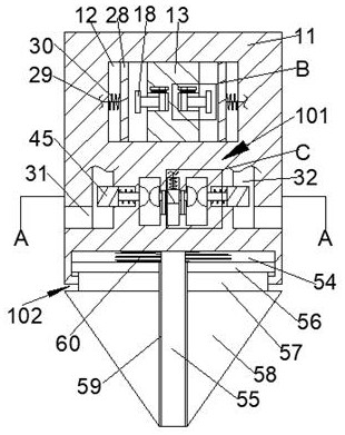
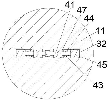
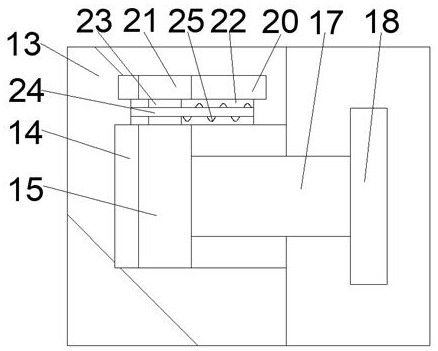
[0017] Combine below Figure 1-4 The present invention is described in detail, wherein, for the convenience of description, the orientations mentioned below are defined as follows: figure 1 The up, down, left, right, front and back directions of the projection relationship itself are the same.

[0018] A vertical axis drill bit for controlling the pumping flow according to the present invention includes a rotating body 11, a centrifugal cavity 12 is arranged inside the rotating body 11, and a centrifugal cavity 12 is fixedly connected between the upper and lower walls of the centrifugal cavity 12. The fixed block 13, the left and right sides of the centrifugal fixed block 13 are respectively provided with centrifugal skateboard chambers 14 with openings facing left and right respectively, and the left and right centrifugal skateboard chambers 14 are respectively provided with centrifugal skateboards 15 capable of sliding left and right The left end surface of the centrifugal ...


PUM


Abstract

The invention discloses a vertical shaft drill bit for controlling slurry pumping flow. The vertical shaft drill bit comprises a rotating machine body, a centrifugal cavity is formed in the rotating machine body, a centrifugal fixing block is fixedly connected between the upper wall and the lower wall in the centrifugal cavity, centrifugal sliding plate cavities with leftward openings and rightward openings are formed in the left side and the right side in the centrifugal fixing block correspondingly, centrifugal sliding plates capable of sliding left and right are arranged in the left centrifugal sliding plate cavity and the right centrifugal sliding plate cavity correspondingly, and the left end face of the left centrifugal sliding plate and the right end face of the right centrifugal sliding plate are fixedly connected with centrifugal sliding plate connecting rods correspondingly. According to the vertical shaft drill bit, the cross-sectional area of a slurry guide cavity is changed, the tightness degree of a connecting rope is changed by centrifugal force firstly, then a left clamping block and a right clamping block get close to each other under the action of elastic force after losing constraint, the cross section area of the slurry guide cavity is increased along with increase of the rotating speed of the drill bit, the slurry pumping effect is improved, meanwhile, thedevice can assist the drill bit in breaking after meeting hard objects, and the construction effect is prevented from being affected.

Description

technical field [0001] The invention relates to the technical field of drilling equipment, in particular to a vertical axis drill bit for controlling the pumping flow rate. Background technique [0002] In our daily life, there will always be engineering construction for urban construction, and this special subject needs to be carried out after engineering exploration and design calculations, and the drilling equipment for exploration is very important. Drilling equipment is Refers to the mechanical devices and equipment used in the specific working conditions of drilling construction. It is mainly composed of drilling rigs and mud pumps. Once the pumping is not timely or the pumping effect is insufficient, the construction efficiency will be affected. It is difficult to control the pumping effect of the existing drill bit, usually need to change the pump pressure to change the flow rate, once the pump pressure is unstable, it will block the mud and affect the construction p...

Claims


Application Information

Patent Timeline
Patent Type & Authority Applications(China)
IPC IPC(8): E21B7/04E21B10/60
CPCE21B7/04E21B10/60
Inventor 周丽榭
Owner 东阳宋辰传动科技有限公司
Why Eureka
Try Eureka