Turbine rotor system

A technology of rotors and turbines, applied in the directions of preventing leakage, supporting elements of blades, engine elements, etc., which can solve the problems of long balance disc length, large air leakage of balance disc, and poor unit safety.

Inactive Publication Date: 2021-01-22
SHANGHAI POWER EQUIP RES INST
View PDF4 Cites 4 Cited by
  • Summary
  • Abstract
  • Description
  • Claims
  • Application Information

AI Technical Summary

Problems solved by technology

[0003] The purpose of the present invention is to provide a turbine rotor system to solve the problems of large air leakage from the balance plate of the existing turbine rotor system, the length of the balance plate is long, and the safety of the unit is poor

Method used


Image

  • Turbine rotor system

Examples


Embodiment Construction

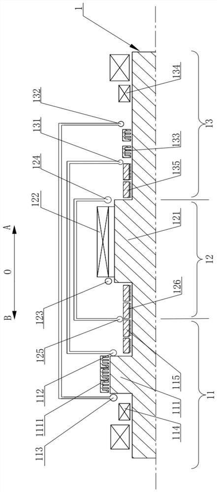
[0028] The present invention will be further described in detail below in conjunction with the accompanying drawings and embodiments. It should be understood that the specific embodiments described here are only used to explain the present invention, but not to limit the present invention. In addition, it should be noted that, for the convenience of description, only some structures related to the present invention are shown in the drawings but not all structures.

[0029] In the description of the present invention, unless otherwise clearly specified and limited, the terms "connected", "connected" and "fixed" should be understood in a broad sense, for example, it can be a fixed connection, a detachable connection, or an integrated ; It can be a mechanical connection or an electrical connection; it can be a direct connection or an indirect connection through an intermediary, and it can be the internal communication of two components or the interaction relationship between two ...


PUM


Abstract

The invention belongs to the technical field of turbine rotating machinery, and discloses a turbine rotor system which comprises a rotating shaft, and a first low-temperature area, a high-temperaturearea and a second low-temperature area are sequentially arranged in the axial direction of the rotating shaft; a balance disc is arranged in the first low-temperature area of the rotating shaft and sleeved with a first seal; a first air inlet is formed in the first low-temperature area of the rotating shaft and used for communicating with a cooling air source so as to cool the first seal; a turbine rotor is arranged in the high-temperature area of the rotating shaft, and blades are arranged on the periphery of the turbine rotor; and a second air inlet is formed in the high-temperature area ofthe rotating shaft and used for providing high-temperature air to drive the blades to drive the rotating shaft to rotate. According to the turbine rotor system, the air leakage amount of the balance disc can be reduced, the length of the balance disc is decreased, accordingly, the span of the rotating shaft is shortened, and the unit safety is improved.

Description

technical field [0001] The invention relates to the technical field of turbine rotating machinery, in particular to a turbine rotor system. Background technique [0002] The supercritical carbon dioxide turbine rotor is a rotor suitable for power generation equipment. At present, the balance plate and the turbine rotor of the existing rotating shaft are located in the high temperature section of the rotating shaft. When the rotating shaft is working, as the operating temperature increases, the balance plate The amount of air leakage will be greatly increased, which will greatly reduce the efficiency of the system. Increasing the length of the balance plate can reduce the amount of air leakage, but the high temperature section of the rotor will be too long, which will make the structural design of the rotor difficult, and will also affect the safety of the rotor unit performance. Contents of the invention [0003] The purpose of the present invention is to provide a turbin...

Claims


Application Information

Patent Timeline
Patent Type & Authority Applications(China)
IPC IPC(8): F01D5/02F01D5/08F01D11/00
CPCF01D5/027F01D5/08F01D11/00
Inventor 李振亚郑开云赵峰张天博叶晶
Owner SHANGHAI POWER EQUIP RES INST
Why Eureka
Try Eureka