Hydroelectric generation device for helping fishes to migrate

A hydroelectric power generation device and fish technology, which is applied in the directions of hydroelectric power generation, fishing, agricultural fishing, etc., can solve the problems of flooding of animals and plants, decrease in the number of fish, and river pollution, so as to ensure normal use and improve service life. , to ensure the effect of the ecosystem

Inactive Publication Date: 2021-01-22
福州鼓楼花旦净电子科技有限公司
View PDF0 Cites 0 Cited by
  • Summary
  • Abstract
  • Description
  • Claims
  • Application Information

AI Technical Summary

Problems solved by technology

[0002] Hydroelectric power generation is a science and technology that studies technical and economic issues such as engineering construction and production operation that convert water energy into electrical energy. It is the mechanical energy of the water wheel, and then the mechanical energy is used to drive the generator to obtain electricity; hydropower generally stores the water flow by building a dam, but the existence of the dam will hinder the fish from migrating, which will make the river flow The quantity of fish decreases in a large number, thereby slowly destroying the ecological system of the river, causing a large number of animals and plants with fish as natural enemies to flood in the river, thereby causing pollution of the river and increasing the economic cost of cleaning the river. The present invention explains A hydroelectric power generation device that helps fish migrate, which can solve the above problems

Method used


Image

  • Hydroelectric generation device for helping fishes to migrate
  • Hydroelectric generation device for helping fishes to migrate
  • Hydroelectric generation device for helping fishes to migrate

Examples


Embodiment Construction

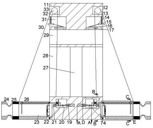
[0019] Combine below Figure 1-6 The present invention is described in detail, wherein, for the convenience of description, the orientations mentioned below are defined as follows: figure 1 The up, down, left, right, front and back directions of the projection relationship itself are the same.

[0020] A hydroelectric power generation device for helping fish to migrate according to the present invention includes a wall 11, a turbine chamber 28 penetrating left and right is arranged in the wall 11, and a turbine 27 is arranged on the inner wall of the turbine chamber 28, so that The upper side of the turbine cavity 28 is provided with a drainage cavity 29 through left and right, and the upper side of the drainage cavity 29 is partially communicated with a hinged cavity 31 that is symmetrical to the left and right of the turbine 27 and whose opening is far away from the axial center of the turbine 27. The upper side of the hinge chamber 31 is provided with an upper transmission...


PUM


Abstract

The invention discloses a hydroelectric generation device for helping fish to migrate. The hydroelectric generation device comprises a wall body, a left-right through turbine cavity is formed in the wall body, a turbine is rotatably arranged on the inner wall of the turbine cavity, and a left-right through drainage cavity is formed in the upper side of the turbine cavity. Hinging cavities which are in bilateral symmetry with respect to the turbine and provided with openings away from one side of the axis of the turbine are formed in the upper side part of the drainage cavity in a communicatingmode, upper transmission cavities with openings away from one side of the axis of the turbine are formed in the upper sides of the hinging cavities, and power bevel gear cavities which are in bilateral symmetry with respect to the axis of the turbine are formed in the lower side of the turbine cavity. Fish at the hydroelectric generation position is fished and conveyed to the other position, thefish is prevented from being extruded by a turbine unit when passing through a hydroelectric power station, meanwhile, normal use of the turbine unit can also be guaranteed, the service life of the turbine is prolonged, the hydroelectric generation device can help the migrating fish to cross over the turbine unit, and therefore, smooth migrating and spawning of the fish can be protected.

Description

technical field [0001] The invention relates to the related field of hydroelectric power generation equipment, in particular to a hydroelectric power generation device for helping fish to migrate. Background technique [0002] Hydroelectric power generation is a science and technology that studies technical and economic issues such as engineering construction and production operation that convert water energy into electrical energy. It is the mechanical energy of the water wheel, and then the mechanical energy is used to drive the generator to obtain electricity; hydropower generally stores the water flow by building a dam, but the existence of the dam will hinder the fish from migrating, which will make the river flow The quantity of fish decreases in a large number, thereby slowly destroying the ecological system of the river, causing a large number of animals and plants with fish as natural enemies to flood in the river, thereby causing pollution of the river and increasi...

Claims


Application Information

Patent Timeline
Patent Type & Authority Applications(China)
IPC IPC(8): F03B13/00F03B11/00A01K69/04
CPCA01K69/04F03B11/00F03B13/00Y02E10/20Y02P60/60
Inventor 郭春理
Owner 福州鼓楼花旦净电子科技有限公司
Why Eureka
Try Eureka