Hydraulic vibration reduction mechanism with variable restoration damping based on swing motor

A swing motor and hydraulic damping technology, which is applied in the field of hydraulic damping, can solve the problems of car body damage, affecting ride comfort, etc., achieve the effects of reducing the degree of deformation, reducing the possibility of gaps, and improving cycle efficiency

Pending Publication Date: 2021-01-22
郭怀宝
View PDF1 Cites 0 Cited by
  • Summary
  • Abstract
  • Description
  • Claims
  • Application Information

AI Technical Summary

Problems solved by technology

[0004] When the swing motor is actually used, the blades swing back and forth with the ups and downs of the car, and the damping force value formed by the blades at the same reciprocating swing angle is the same, that is, the swing motor will give the car the same degree of cushioning when the car rises and falls. In the actual use process, it is found that when the swing motor will give the car the same degree of cushioning when the car is up and down, for the passengers, the bumpy f

Method used


Image

  • Hydraulic vibration reduction mechanism with variable restoration damping based on swing motor
  • Hydraulic vibration reduction mechanism with variable restoration damping based on swing motor
  • Hydraulic vibration reduction mechanism with variable restoration damping based on swing motor

Examples


Embodiment 1

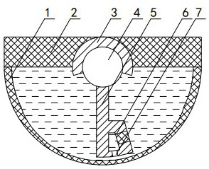
[0033] Such as figure 1 As shown, a hydraulic vibration damping mechanism with variable recovery damping based on a swing motor (hereinafter referred to as a vibration damping mechanism) includes a swing motor cylinder 1, which is semicircular and has an upper end opening. A swing motor top cover 2 is provided, and after the swing motor top cover 2 and the swing motor oil cylinder 1 are installed together, an airtight oil chamber is formed inside the swing motor oil cylinder 1 . At the center of the inner surface of the swing motor top cover 2 located in the oil chamber, there is a mounting groove that runs through the front and rear of the swing motor. In the mounting groove, a limit cover 3 with a fan-shaped cross section is arranged, and the opening of the limit cover 3 faces the oil chamber. One side and the radian of the limit cover 3 is greater than π.

[0034] The swing motor shaft 4 of the swing motor is installed in the opening of the limit cover 3 towards the oil ch...

Embodiment 2

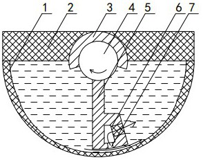
[0044] The difference between embodiment and embodiment 1 is: as Figure 6 As shown, the cross section of the swing motor cylinder 1 of the swing motor is circular, and the swing motor shaft 4 is arranged at the center of the swing motor cylinder 1 and drawn out from the side of the swing motor cylinder 1 . Two limit covers 3 are arranged symmetrically on both sides of the swing motor shaft 4 , the arcs of the two limit covers 3 are equal and the sum of the arcs is greater than π. Two vanes 5 are arranged symmetrically on both sides of the swing motor shaft 4 , and the two vanes 5 pass through the two spaces formed by the two spacer covers 3 respectively and then attach to the inner surface of the swing motor cylinder 1 .

[0045] Two oil chambers are formed at intervals of the swing motor oil cylinder 1 by two vanes 5 . A partition 8 is provided. One end of the partition 8 is fixed on the limit cover 3, and the other end is fixed on the inner surface of the swing motor cylin...

Embodiment 3

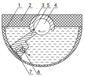
[0048] The difference between this embodiment and embodiment 1 is: as Figure 7 As shown, in this embodiment, two oil ports 9 are respectively opened on the swing motor top cover 2, and the two oil ports 9 communicate with the two oil chambers in the swing motor cylinder 1 respectively. By setting the oil ports 9, A closed oil circuit can be formed through pipelines outside the swing motor, and other devices, dampers, etc. can be set in the oil circuit.


PUM


Abstract

The invention discloses a hydraulic vibration reduction mechanism with variable restoration damping based on a swing motor, and belongs to the technical field of hydraulic vibration reduction. The hydraulic vibration reduction mechanism comprises a swing motor oil cylinder (1), an oil chamber is arranged in the swing motor oil cylinder (1), a swing motor rotating shaft (4) is arranged in the oil chamber, a blade (5) is connected to the swing motor rotating shaft (4), the swing motor rotating shaft (4) drives the blade (5) to swing in the oil chamber in a reciprocating mode, and at least one arc-shaped channel is formed between the blade (5) and the inner wall of the swing motor oil cylinder (1) at intervals. The hydraulic vibration reduction mechanism is characterized in that a one-way conduction mechanism is installed on the blade (5), and the one-way conduction mechanism is closed along with the restoration movement of the swing motor rotating shaft (4). According to the hydraulic vibration reduction mechanism with the variable restoration damping based on the swing motor, the one-way conduction mechanism is arranged on the blade, so that the flow area of oil is blocked to a certain extent during restoration, and the damping force value during restoration is changed.

Description

technical field [0001] The invention relates to a hydraulic damping mechanism with variable restoration damping based on a swing motor, which belongs to the technical field of hydraulic damping. Background technique [0002] Hydraulic vibration damping is a common vibration reduction method in the automotive field. The output end and the main body of the automobile hydraulic shock absorber are respectively installed on the body and the wheel assembly. Generally, a shock absorber piston is arranged in the automobile shock absorber. During the reciprocating movement, a valve plate mechanism is set in the piston, so when the piston reciprocates, the hydraulic oil on both sides of the piston will reciprocate through the piston through the flow hole on the piston in the opposite direction to the piston, thus playing a role Damping effect. [0003] A technical solution is proposed in the Chinese patent with the application date of February 5, 2018, the application number 2018201...

Claims


Application Information

Patent Timeline
IPC IPC(8): F16F15/16
CPCF16F15/161F16F15/162
Inventor 郭怀宝
Owner 郭怀宝
Why Eureka
Try Eureka